
|
|
'ADD3' Add-on Board
|
DESCRIPTION:
ADD3 is an add on 'daughter board'. ADD3 is 'dumb'. It needs an external device to control it. It is mainly intended to add features to Rx65 but can be used with other circuits.
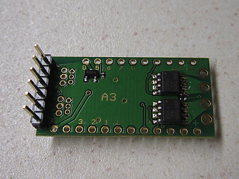
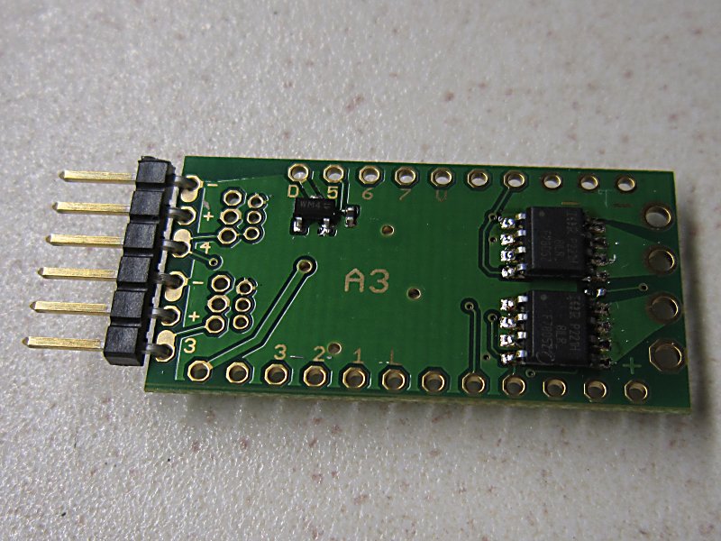
SERVO CONNECTOR OPTIONS:
ADD3 can have two connectors for servos. These make most sense on the BEC version. The BEC is a Battery Eliminator Circuit which provides 1A at 5v to power servos. It derives its power from the battery powering the receiver. It can only reduce voltage so it is intended for use with 6-9v batteries (2S lipos, 5-6 nicads, PP3). For higher voltages use an external UBEC or SBEC.
|
Vertical |
Connector |
Horizontal |
Comment |
|
Standard 2.54mm (0.1") |
|
. |
|
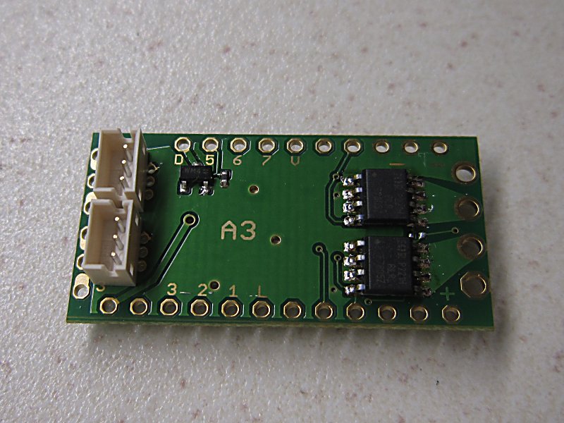
JST ZH 1.5mm |
|
Always check servo lead polarities. This horizontal JST option has a pin order that is normally considerd to be incorrect. |

|
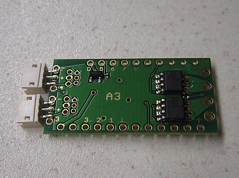
Molex Picoblade 1.25mm |
|
. |
INSTALLING ADD3 on Rx65b:
|
|
|
|
|
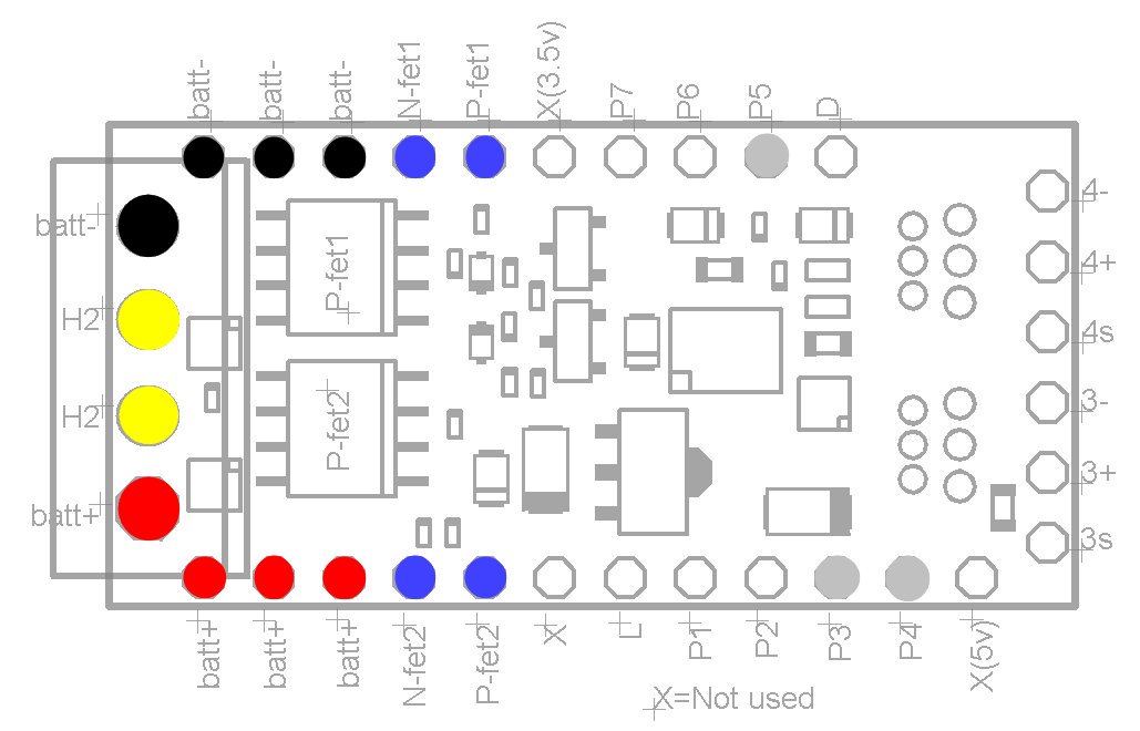
Functions:
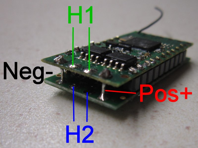
The purpose of the connections shown in the 'Functions' illustration are as follows:
* RED holes are battery positive.
* BLACK holes are battery negative.
* YELLOW holes are H2 (motor).
* BLUE holes control H2.
* GREY holes control the two servo plugs (P3/P4) and output D (P5).
The other holes are not connected to anything on ADD3.
Programming:
ADD3 is normally supplied pre-installed. If not, the number of outputs and how they are configured must be set first. The easiest two options for doing this are as follows:
1. Change variant/board with Prog2 (Variants '1-27').
2. Change variant/board with programming (Menu 9).
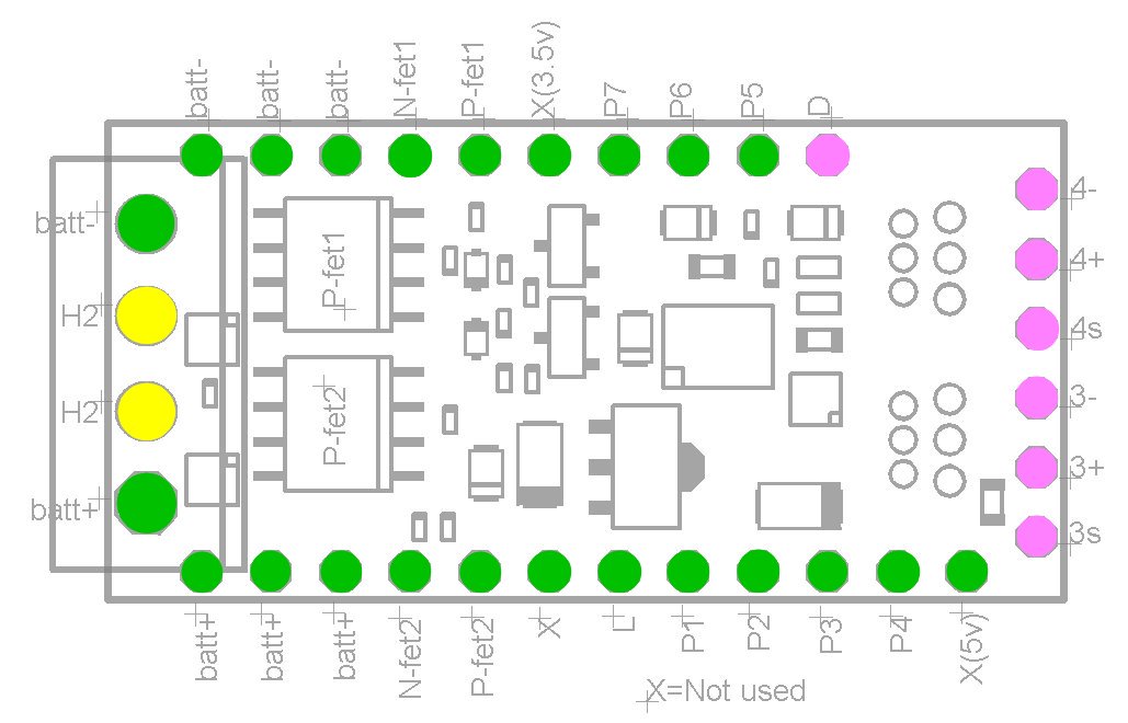
Assembly:
ADD3 is usually soldered to the core receiver with 0.1" pin headers in most of the 'green' holes:
* GREEN holes in the 'Assembly' illustration above can be connected to the receiver (some are optional; see below).
* YELLOW holes MUST be connected to the receiver for 6A1.
* YELLOW holes MUST NOT be connected to the receiver for 3A2.
* PINK holes MUST NOT be connected to the receiver.
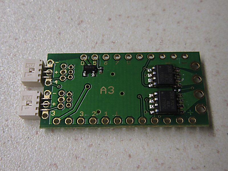
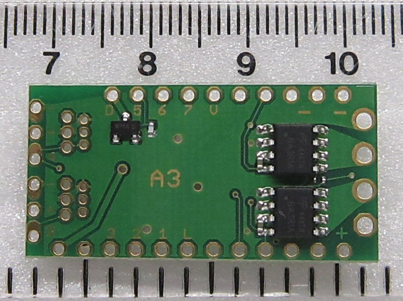
1. The top side of the Rx with led and the largest black chip (Xmega) is one 'outside' surface. The side of ADD3 marked 'A3' is the other outside surface.
2. Attach servo plugs or sockets to ADD3 if required.
3. Power must be supplied to both ADD3 and the core receiver. Four positive (+) and four negative (-) holes exist. At least one of each must be connected.
4. The ADD3 ESC (H2) is controlled with P8/9/10/11. These must be connected to use H2.
5. Connect the motor outputs together if they are are to be used in parallel (6A1). They must NOT be connected if they are to be used as two independant outputs (3A2).
6. P3/4/5 must be connected if the servo outputs or 'D' are to be used.
7. All other P outputs can be connected if desired/easiest.