
|
|
Multi-Position Channel
|
DESCRIPTION
This page has examples for setting Multi-Position channel (programming Menu 12/13)
Prog4 is required to change all these settings in DT receivers.
EXAMPLE 1
7 leds, 1 channel, 4 switch positions, Momentary and Latching switch actions, with and without Trigger buttons
Positions 1, 2 and 3 are used as a menu, with two actions on each using the trigger buttons (6 leds)
Position 4 is used to make one led toggle each time the switch is in that position
|
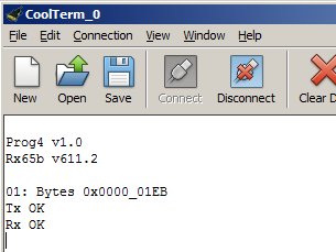
Send file to set 'Control' settings and configure 7 outputs dt-multi2a.txt for receivers with 2-way programming capability (Rx65b/Rx47) dt-multi2b.txt for receivers with 1-way programming capability |
EXPLANATION
The Multi-Position feature allows one channel to control up to 36 things. These comprise switching outputs on/off or changing settings in the receiver. It is intended to be used with a 12-position rotary switch and two trigger buttons (T1/T2). Tx72 and Tx74 have these switches. Each of the 12 positions can trigger an action direct or be used as a 'menu' with the trigger buttons causing actions to occur.
Transmitters with Selecta have a 12-position switch for that function. Two trigger buttons (T3/T4) can be installed to control two actions. The 12-way switch continues to be used only for Selecta.
Menu 12 is used to set up the controlling channel. It is also used to switch outputs on/off with this feature. Menu 13 is used to set up 'actions'. These either change settings in the receiver or trigger other features.
CIRCUIT DIAGRAM
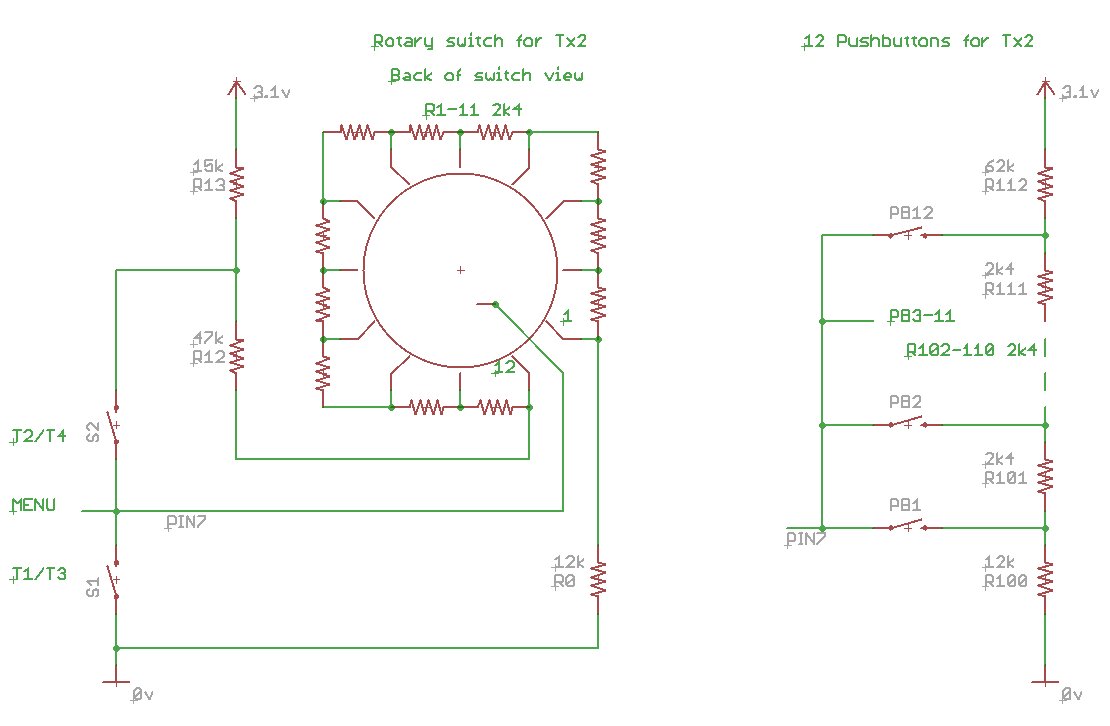
multi-1a.pdf shows 12-way switch and 12 pushbutton approaches
OTHER EXAMPLES
dt-menu1a.txt Activate 'menu' on Tx72/Tx74 with several features
dt-menu2a.txt Activate T3/T4 on Tx22/Tx24
The video below shows an example of 'Menu' in use. Using two leds to illustrate motor control, this shows center off motor control initially to show how the leds work, then an emergency stop at position 12, then changes to motor direction a few times, battery voltage display (5v), increasing/reducing startup motor power. It also shows two flash sequences (can only be created on certain receivers) while controlling motor with the throttle knob. Notice how some things are triggered directly by the position of the switch (emegency stop and battery volts flash) and the others are triggered with the buttons.