
|
|
DT Receiver - Rx32d Instructions - v3.5.x
|
|
|
1. GENERAL:
3-10v may be connected with correct orientation to +/- points.
The Rx is not insulated so take care to avoid short circuits.
The PCB is thin so do not bend it or exert great force on it.
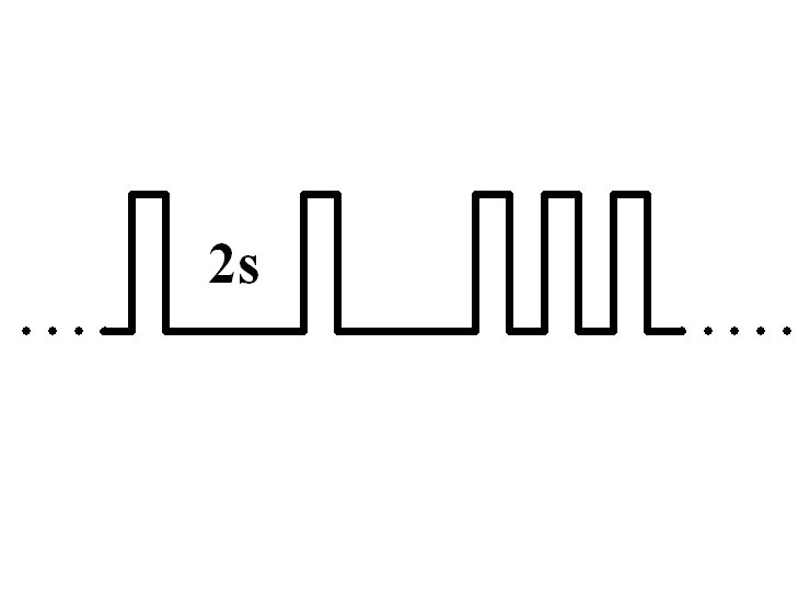
2. LED:
Led On = perfect reception (real-time indicator).
1 flash = Scanning (~2sec between flashes; wrong model if never stops).
2 flash = Brownout (receiver voltage went too low; check battery/servo load).
3. FAILSAFE:
Outputs are not driven (do nothing) on startup and while scanning.
Outputs 'hold' on short signal losses (<1sec) and then do nothing (>1s).
From v352 the Ch1 Throttle output has a failsafe output learned during binding.
4. BINDING:
1. Switch Rx on and wait ~20s until led flickers fast.
2. Place the Ch1 Throttle stick in the position needed for failsafe.
3. Switch Tx on in bind mode and Rx led should flash slowly and then go solid.
Change distance or angle between Tx/Rx if binding does not work.
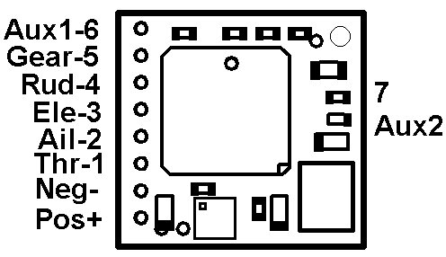
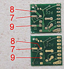
5. OUTPUTS:
Pads 1-9 will normally be used for servos or an external ESC.
Up to v352 options exist for 7ch Serial and 7ch SumPPM on Pad 3.
From v353 options exist for 9ch Serial and 7ch SumPPM on Pad 3.
It is likely to be necessary to rebind after changing between 7 and 9ch features.
6.1 PROGRAMMING:
|
|

|
1. Switch Transmitter on.
2. Make sure Ch3 (Elevator) is normal direction (not reversed).
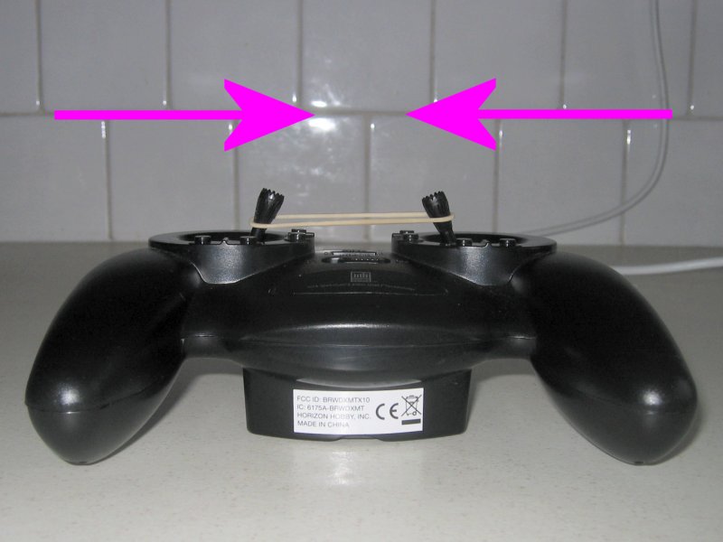
3. Hold left/right sticks (Ch2/4) in towards middle of Tx.
4. Switch Receiver on and wait for the Led to flicker very fast.
5. Center all sticks.
6. The led flashes the setting for the first 'Level' (eg: 1-flash = LVC disabled, 2-flash = LVC enabled).
7. Yes = push the Ch3 (Elevator) stick forward (to top of Tx) to accept this and advance to next Level.
8. No = pull the Ch3 (Elevator) stick back (to bottom of Tx) to see next option for same Level.
9. Continue through all Levels until Led comes on solid.
10. Settings are saved automatically at the end so switch off at any time to abort.
11. Say 'yes' to every item to just see what is currently set.
|
This example shows how to set up twin-steer mix on Rx31d. Although not relevant to this receiver the technique is the same: Level 1: 1-flash NO, 2-flash NO, 3-flash YES = Option 3 (25%) & move to next level Level 2-6: YES to all. |
6.2 PROGRAM LEVELS / NUMBER OF FLASHES:
Level 1: Low Voltage Cutoff (not relevant)
1 = Disabled
2 = Enabled (Default)
Level 2: Servo/Sum-PPM outputs
1 = Sum-PPM on Pin3
2 = Serial on Pin3
3 = Servo outputs on all pads (Default)
Level1: 2-flash
Elevator up/forward = yes/next level
Level2: 3-flash (servo)
Elevator down (bottom) = no/next option/same level
Level2 1-flash (sumppm)
Elevator up/forward=yes
Led on solid = complete