
|
|
DT Receiver - Rx43d-4 - v520 Instructions
|
|
|
|

|
1. DEFAULT SETUP
- Car with 1-4 motors (reversable), 1 servo (steering) and 1-3 Lights.
- Train with 1-4 motors (reversable) and 2-4 Lights.
- Plane requires more changes.
- Requires ADD1 to use H4 with motors and actuators.
- All outputs can be customised / re-configured.
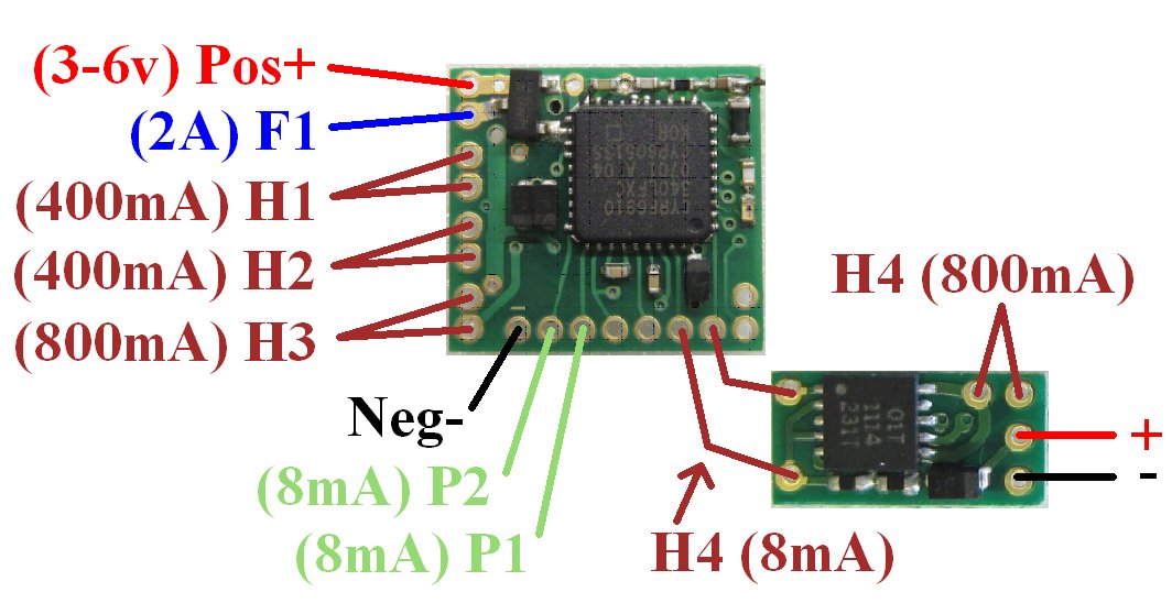
| Output | Type | Channel | Other |
| H1: | Motor 1 (center off) | Ch1 | 400mA |
| H2: | Motor 2 (center off) | Ch2 | 400mA |
| H3: | Motor 3 (center off) | Ch3 | 800mA |
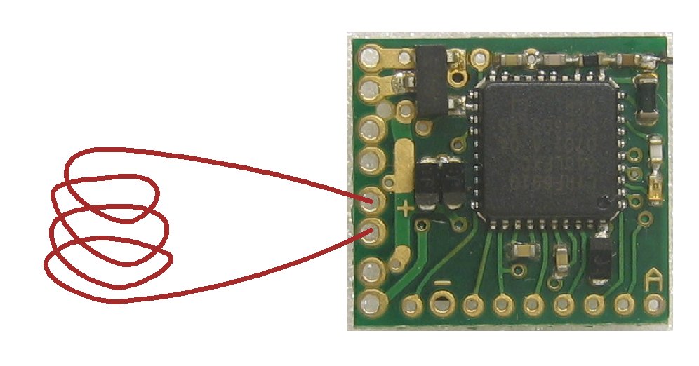
| H4: | Motor 4 (center off) | Ch4 | 8mA without ADD1, 800mA with ADD1 |
| F1: | Variable voltage / on/off Switch | Ch6 | 2A |
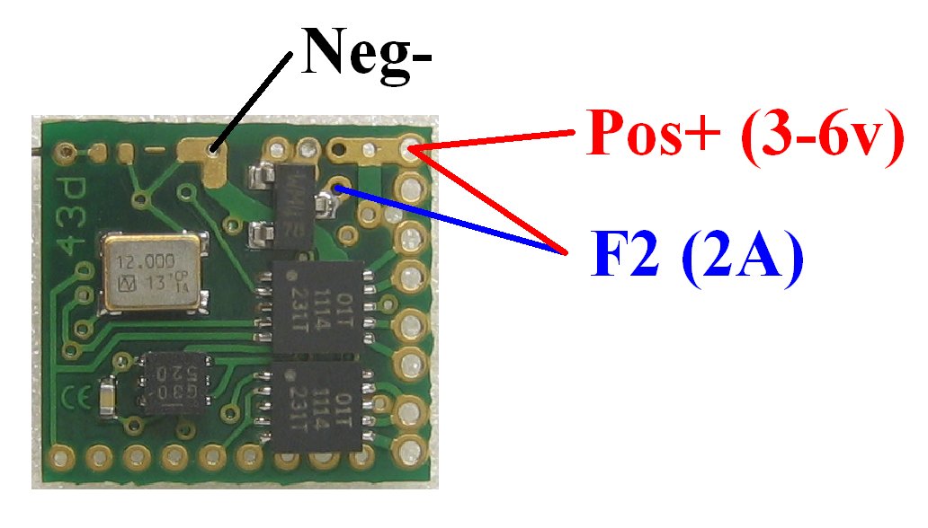
| F2: | Variable voltage / on/off Switch | Ch7 | 2A |
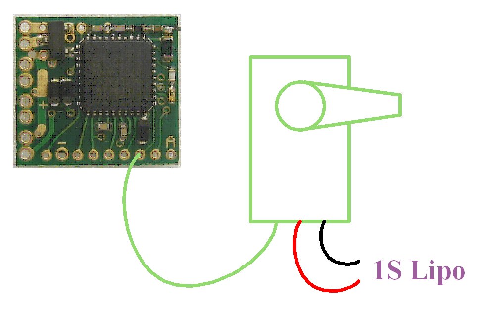
| P1: | Servo | Ch2 | |
| P2: | On/off led | Ch1 up | |
| Arming/Activation: | Mid-stick to enable | Ch3 | |
| LVC |
Mid-stick to acknowledge 5-flash |
Ch3 | |
| LED2 | External LED to show receiver activity | P2 |
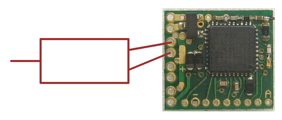
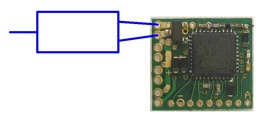
2. EXAMPLE CONNECTIONS:
|
|
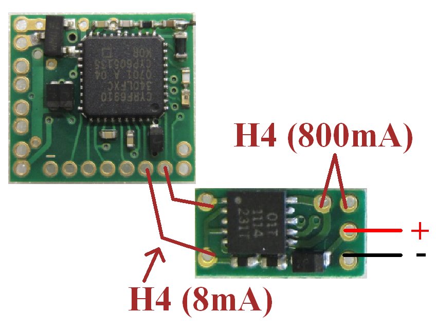
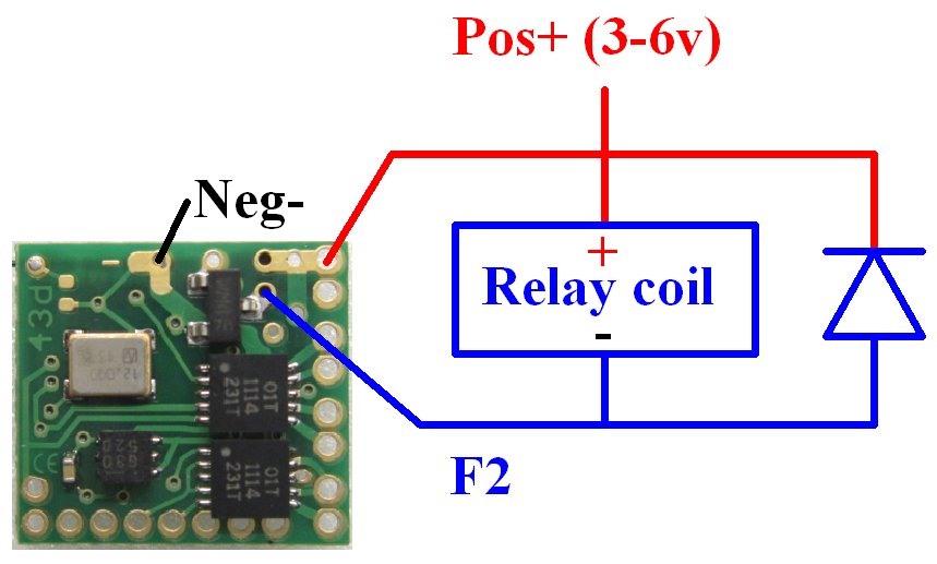
motor/actuator |
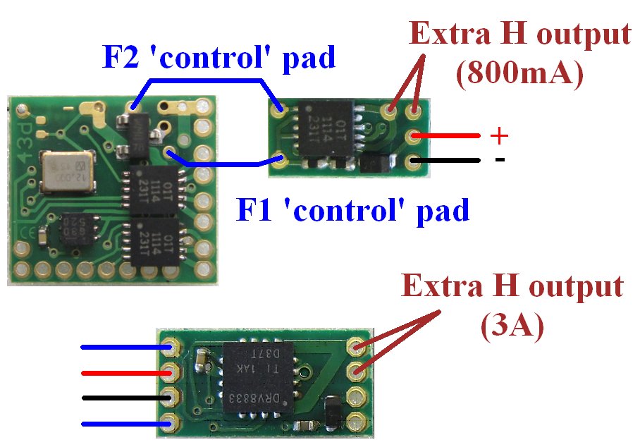
for extra H output |
|
|
|
|
|
LEDs with 1S Lipo:
Led's driven from P outputs only require a current limiting resistor (8mA max).
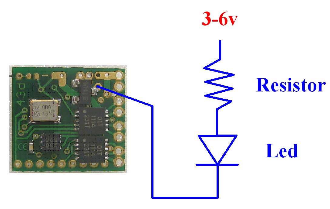
Led's driven from F outputs only require a current limiting resistor (2A max).
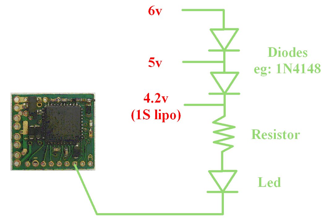
LEDs with 5-6v:
'P' outputs are 3v when 'off' and 0v when 'on'. So when used with higher voltages, the leds driven from P outputs also need diodes to reduce the voltage. This is because 5 or 6v is high enough above the 3v output to make Leds conduct even when P outputs are 'off'. An example is shown in the Led (P1) diagram.
Led's driven from F outputs only require a current limiting resistor when operated off any voltage up to 6v.
GRAIN of WHEAT:
Grain of Wheat bulbs usually draw >8mA so are not suitable for use with P outputs (unless buffered with a transistor).
Grain of Wheat bulbs can be driven from F outputs. F outputs allow the intensity to be varied with stick movement or 'Travel Adjust'.
3. CHANGING OUTPUTS:
All outputs can be customised / re-configured:
PROGRAMMING
4. GENERAL:
The Rx is not insulated.
The PCB is thin so do not bend it.
5. LED:
Led On = perfect reception (real-time indicator).
1 flash = Scanning (~2sec between flashes; wrong model if never stops).
2 flash = Selecta (model not active).
5 flash = Brownout (receiver voltage went too low; check battery/servo load).
6. FAILSAFE:
Outputs are not driven (do nothing) on startup and while scanning.
Outputs 'hold' on short signal losses (<3sec) and then do nothing (>3s).
7. BINDING:
1. Switch Rx on and wait ~20s until led flickers fast.
2. Switch Tx on in bind mode and Rx led should flash slowly and then go solid.
3. Change distance between Tx/Rx if binding does not work.