
|
|
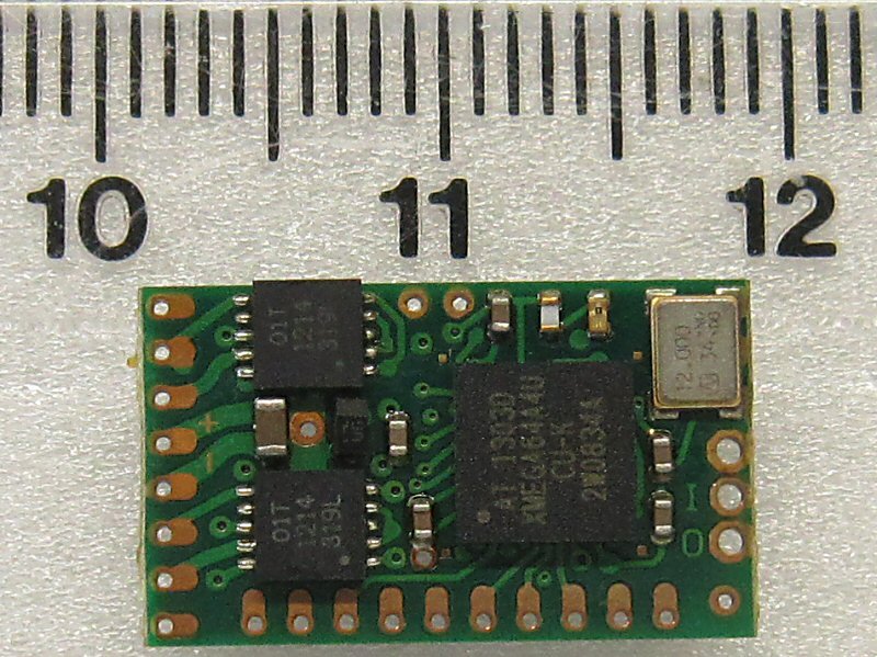
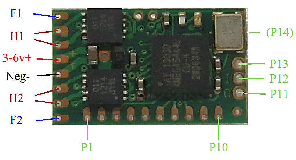
Rx47 - Instructions
|
|
|

|

|
1. DEFAULT SETUP
| Output | Type | Channel | Other |
| H1: | Motor | Ch2 center off | |
| H2: | Motor | Ch3 center off | |
| F1: | Simple PWM | Ch1 low off | Can be used as 'P15' and 'H5' |
| F2: | Simple PWM | Ch6 low off | Can be used as 'P16' and 'H5' |
| P1: | Servo | Ch1 | |
| P2: | Servo | Ch2 | |
| P3: | Servo | Ch3 | |
| P4: | Servo | Ch4 | |
| P5: | Left indicator | Ch4 left <1s on | Ch2 steering/auto cancel |
| P6: | Right indicator | Ch4 right <1s on | Ch2 steering/auto cancel |
| (P5/P6): | Hazards (Left+Right) | Ch4 left >2s toggle on/off | |
| P7: | Flasher (0.5s) | Ch4 right >2s toggle on/off | |
| P8: | Driving lights | Ch5 toggle on/off | |
| P9: | Brake light | Ch3 auto activate | |
| P10: | Reverse light | Ch3 auto activate | |
| P11: | Led | Ch6 toggle on/off | Can be used as 'H4' with ADD1 |
| P12: | Servo | Ch5 | Can be used as 'H4' with ADD1 |
| P13: | Servo | Ch6 | Can be used as 'H3' with ADD1 |
| P14: | Servo | Ch7 | Can be used as 'H3' with ADD1 |
| Arming/Activation: |
H2 (Ch3 center off) |
Enabled | |
| LVC |
H2 (Ch3 center off) Brake light ON; outputs OFF LED2 5-flash |
Enabled | 'Auto' (3v cut-off from 1S lipo) |
| LED2 | P8 (front light) | Enabled | External LED to show receiver activity |
| XPlus (18ch) | Disabled | Only 12 channels enabled | |
| Selecta | Disabled | ||
| Sleep | Disabled | ||
| PWM frequency | 500Hz |
2. CONNECTIONS:
Battery:
1. The receiver is intended for use with 1S lipos. The MCU operates at 3v with an on-board regulator.
2. The minimum voltage is around 3v. The maximim voltage is 6v.
3. Rx47 has some reverse-polarity protection but it is not 100%. In particular, the h-bridge is not protected. It is better to assume nothing is protected and to use a diode in series with the + or - connections if protection is required.
P outputs:
1. P outputs are rated at 20mA (25mA absolute max). The MCU is rated for 200mA absolute max. So current through all the P outputs must be less than 200mA.
2. By default, P outputs are set up to be 0v when ON and 3v when OFF. This makes them act in a similar way to the F outputs and reduces heat in the receiver. This means leds are normally connected between Positive (+) and Rx47 outputs (with a current-limiting resistor).
3. P outputs can be changed to be 3v when ON and 0v when OFF.
F outputs:
1. F outputs use N-channel fets. These create a path to Ground (0v) when ON and are floating (disconnected) when OFF. Technically this is 'open drain' but is also known as 'open collector'.
2. Fets have three terminals. The outputs (Drain) are connected to the F1/F2 pads. The control inputs (Gates) are connected to the MCU. The third terminal is Ground.
3. F outputs can be used as 'F1' and 'F2'. The Gates are driven with PWM. It is normal to use the F1/F2 pads on the edge of the board. The fets will then be 'in circuit' and have 2A rating.
4. F outputs can be used as 'P15' and 'P16'. This allows more switching options. It may be necessary to connect to the Gates to get full advantage (eg: to drive servos). This would bypass the fet so the rating would be the same as other P outputs (20mA). The rating is still 2A if you connect at the F1/F2 pads (Drain).
H outputs:
1. Rx47 has two on-board h-bridges which allow forward/reverse control of brushed motors and actuators. H1/H2 are both rated at 800mA.
2. H1/H2 can be set to work in 'combo' mode. The outputs can be connected in parallel for a combined 1.6A rating.
3. P13+P14 can be made to act as 'H3' and P11+P12 can be made to act as 'H4'. These can be used to drive an external h-bridge board (eg: ADD1/ADD2) with PWM. The current rating depends on the addon board.
4. 'H5' can be created with F1+F2 set to 'muscle wire' setting. Again this requires an external h-bridge board which has to be driven from the 'Gate' pads.
PWM frequency:
1. The PWM frequency for the H and F outputs can be changed. Higher frequencies may generate more heat. Reduce PWM speed or use heat sinks if Rx47 gets hot.
2. PWM uses 256 step resolution in each direction (512 total).
3. CHANGING OUTPUTS:
All outputs can be customised / re-configured:
PROGRAMMING
4. GENERAL:
The Rx is not insulated. The PCB must not be bent or twisted.
The PCB has 4 layers. So more heat may be needed than normal to solder pads.
Rx47 should work with DSM2 (surface and air) and DSMX. By default up to 12 channels can be used (18 channels if XPlus is enabled in Rx/Tx).
5. LED:
Led On = perfect reception (real-time indicator).
1 flash = Scanning (~2sec between flashes; wrong model if never stops).
2 flash = Selecta (if enabled) model not active.
5 flash = Brownout (receiver voltage went too low; check battery/motor load).
6. FAILSAFE:
Outputs are not driven (do nothing) on startup and while scanning.
Outputs 'hold' on short signal losses (<1sec) and then do nothing (>1s).
7. BINDING:
1. Switch Rx on and wait ~20s until led flickers fast.
2. Switch Tx on in bind mode and Rx led should flash slowly and then go solid.
3. Change distance between Tx/Rx if binding does not work.