
|
|
Rx61-3 Instructions (v6.0.3)
|
|
|
|
1. DEFAULT SETUP
|
Item |
Setting | Details |
|
Purpose: |
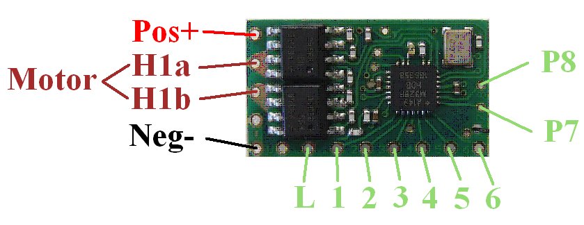
Rx61-3 |
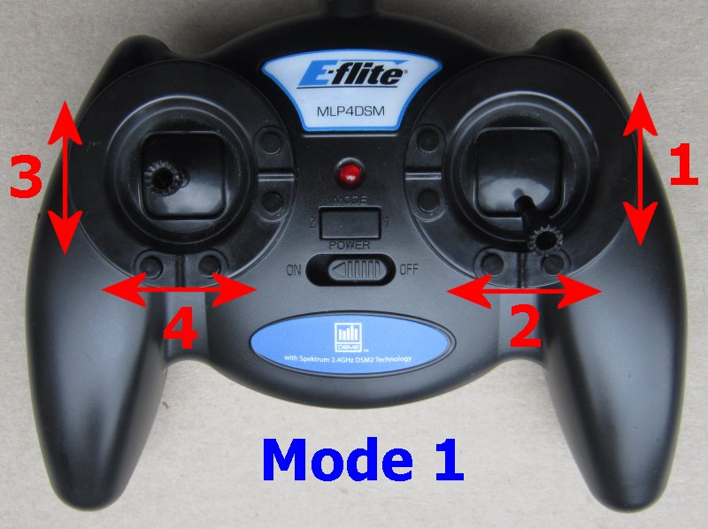
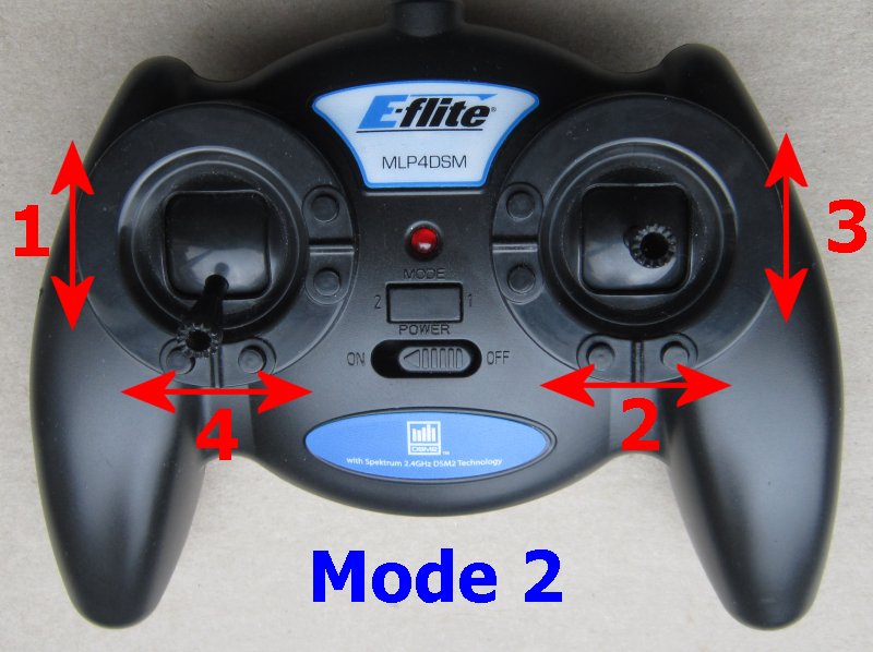
'Car' with joystick transmitter |
|
Red wire positive (+) Black wire negative (-) |
Battery |
3-16v Observe polarities |
|
H1 output Brown wires |
Motor Ch3 (Elevator) |
Integrated forward/reverse ESC for brushed motors Center off |
|
P1 output |
Servo steering (Ch2) |
Standard servo Steering trim picked up at startup for indicators |
|
P2 output |
Driving lights (Ch1) |
Led needs current limiting resistor Ch1 high for on, low for off |
|
P3 output |
Brake light (Ch3) |
Led needs current limiting resistor Activates automatically |
|
P4 output |
Reverse light (Ch3) |
Led needs current limiting resistor Activates automatically |
|
P5 output |
Flashing light (Ch4) |
Led needs current limiting resistor Ch4 right for >2s to activate |
|
P6 output |
Left Indicator (Ch4) |
Led needs current limiting resistor Ch4 left for <2s to activate |
|
P7 output |
Right Indicator (Ch4) |
Led needs current limiting resistor Ch4 right for <2s to activate |
|
P6+P7 |
Hazards (Ch4) |
Ch4 left for >2s to activate |
|
P8 output |
IR4 |
Battery voltage telemetry Infrared led needs current limiting resistor |
|
L input |
Auto-detect |
Monitors single cell lipo when used with a voltage booster |
|
Arming: |
Enabled |
Ch3 to center position (off) |
| LVC | Enabled |
LVC=Low Voltage Cutoff Led 5-flash if triggered Stop and charge battery |
| Inactivity Sleep | Enabled |
Invoked after 1hour Switch off and on to restart |
2. EXAMPLE CONNECTIONS:
|
|
|
|
|
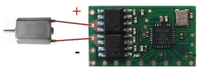
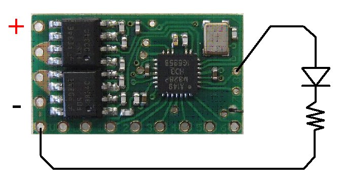
'P' outputs are 3v when on and 0v when off. Led's need resistors to limit current to 20mA but high brightness led's allow a lower current (eg: 2-5mA). Google will reveal how to select resistor values but 220-470ohms will be safe starting values.
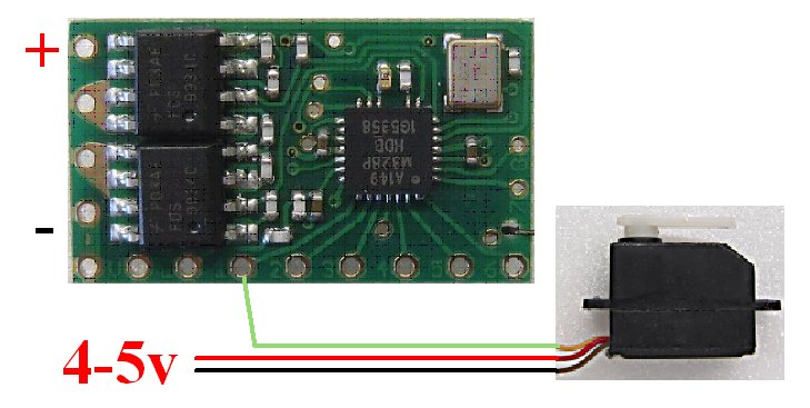
Servos can be powered direct from 1S lipo but 2S is normally too high. A 4 or 5v regulator is usually needed.
The 'Fet' example is how to drive higher currents with a P output. The fet needs to be 'logic-level N-channel' and have low Rds on resistance (eg: <100 milli-ohms) with a 3v Gate drive voltage. The Vds voltage must exceed whatever positive supply you are using (20v and higher is common). The current rating must exceed what ever current you are driving (the higher the 'Amps' rating the better).
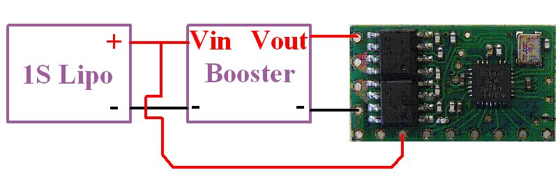
The 'L' pad is intended to monitor a single cell lipo when used with a voltage booster. This allows the receiver and motor to be powered with a boosted voltage and benefit from the convenience of a single lipo. The receiver will auto-detect when a lipo is connected. It will cut power to the motor when the voltage falls to 3v (LVC). The L pad is not intended for use when powering a receiver direct from a single lipo.
3. BINDING
Bind once:
1. Switch Rx on and wait ~20s until led flickers fast.
2. Switch Tx on in bind mode.
3. Rx led should flash slowly; wait for it to go solid.
Change distance between Tx/Rx if binding does not work.
4. LED:
Led On = perfect reception (real-time indicator).
1 flash = Scanning (~2sec between flashes; no signal or not bound if never stops).
5 flash = LVC/Brownout (voltage went too low; check battery/motor load).
5. FAILSAFE:
The motor output is not active on startup and while scanning for a signal.
The motor output 'holds' last known settings on short signal losses (<1sec) and then slows to a stop over 3 seconds.
6. OTHER:
This receiver has other features that are not described.
These are changed using a technique called 'programming':
| Version |
v6.0.3 |