
|
|
Rx61 Overview
|
|
|
|
|
|
|
PCB ID: 61c
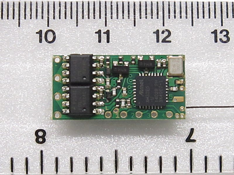
PRODUCT: Rx61
PCB SIZE: 11x22.5mm (0.43x0.9")
PROGRAMMING: v611
ALL FEATURES: v611
CORE RECEIVER:
2.4GHz receiver compatible with DSM2/DSMX including one integrated 1.3A reversable controller for brushed motors (ESC)
3-13v for 1-3S lipo, 1-3 life, 3-8 nicads, 1 PP3
|
Click to enlarge |
Name | GBP | Euro | USD |
H outputs (ESC) |
P outputs (On/Off) |
Instructions (x=Variant 1-22) |
 |
Rx61-x-N Rx61-x-W |
Ł28 Ł30 |
€35 €37 |
$42 $45 |
1 | 5 |
x = 1, 2, 22, 3, 4, 5, 6 |
eg: Rx61-2-N (Variant 2, no wires)
eg: Rx61-22-W (Variant 22, Wires for motor and battery)
VARIANTS:
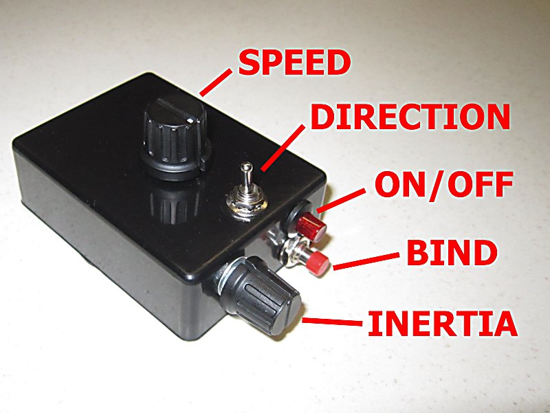
Rx61-1: Settings for 'trains' with separate controls for speed and direction
Rx61-2: As above but one control for throttle (center off)
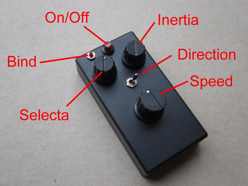
Rx61-22: As above but with Selecta enabled (for use with Tx22/24)
Rx61-3: Servo outputs, Cars/Boats with Tx24
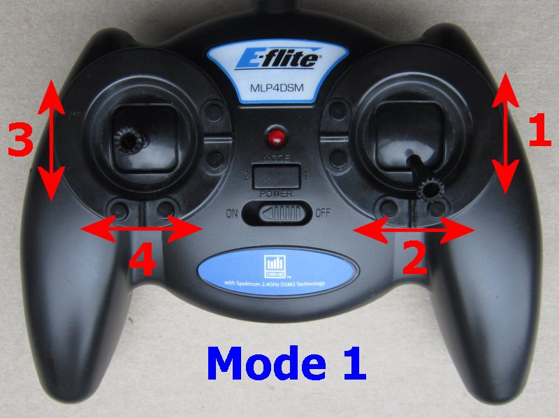
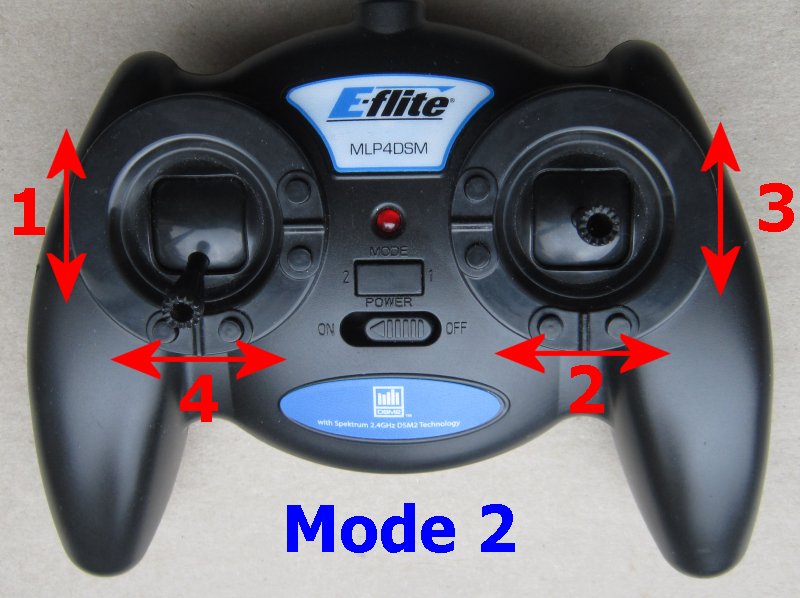
Rx61-4: Settings for 'cars' with Joystick transmitter
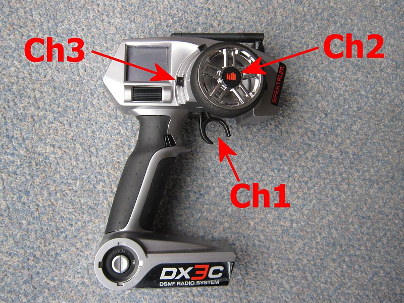
Rx61-5: Settings for DX3 transmitter
Rx61-6: Settings for 'boats' with Joystick transmitter
OPTION:

|
W = Wires for motor/battery (+ heatshrink covering) |
COMMENTARY:
This page is for Rx61c. This receiver replaces the following previous versions:
Rx61a
Rx61b
Standard:
The simplest way to start is with a 'wired' version of the receiver (eg: Rx61-22-W with Tx22-Built). Connect the red/back to a battery and two other wires to the motor, bind once and that's about it. Make sure you read the instructions for your variant (links above). Make sure you disconnect train motors from wheel pickups.
More advanced info:
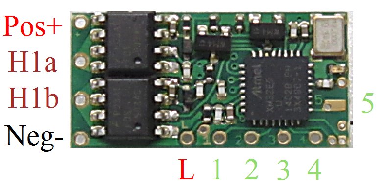
Rx61 is intended for surface vehicles which require forward and reverse motor control. For brushed motors this is achieved with an H-Bridge. The motor output is abbreviated H1. This is often referred to as an ESC (Electronic Speed Controller). It has 256 step resolution in both directions (512 total). It controls speed with PWM which by default is set to its fastest (quietest) 16kHz setting.
The H1 output can handle up to 1.3A current without heat sinking at voltages between 3 and 13v. Current is measured with motor stalled. The main constraint with current is heat in the receiver. Higher currents may be possible if a heatsink is added and is helped with the 120Hz PWM frequency. The receiver is built with 20v components. It should be possible to use it a little above 13v but this would require lower motor currents and/or heat-sinking. Induced voltages may be higher than the power source so it would not be wise to try to use it anywhere close to 20v.
'P' outputs are 'pads' with 'logic' type outputs. Pads are simply solder points for controlling external things. Logic outputs are either on or off (also known as high/low and 3.3v/0v in voltage terms). The action can be inverted so 'On' can mean 0v or 3.3v. P outputs are used to provide servo signals direct to the white/yellow lead on a servo. They can often directly control triggers on external sound cards. They are also used to drive leds but need a resistor to limit current to no more than 20mA.
'Variants' are simply 'configurations'. Each variant is a different combination of settings to better match common needs. Although these are described as 'car/train/boat' any variant can be used for anything. All settings can be changed in a process called 'programming'.