
|
|
Rx63 - Programming v6.0.3
|
1. PROGRAMMING APPROACH:
Settings in the Rx can be changed using a standard Tx or a special Programa device (PROG1). Both use the structure in the table below. One output or feature (ie: one row in the table) is programmed at a time. Levels 1-2 usually select the output and Levels 3-5 change its characteristics. [KEYWORDS] provide links to detailed descriptions of each feature. The 'Tx' column is for 'Tx Change' mode.
2. PROGRAMMING OPTIONS:
|
Level 1 |
Level 2 |
Level 3 |
Level 4 |
Level 5 |
Information | Tx |
|
|
||||||
|
Menu 1 (Motor) |
Output number: | Output type: | Channel number: | Other: | ||
| 1 flash | 1 flash = H1 |
1 flash = Center off (1 stick, half each way) [M_TYPE_1] |
1-10 flash = Channel |
1/2 stick forward, 1/2 stick back |
2 | |
| 1 flash | 1 flash = H1 |
2 flash = Low off (2ch: power + direction) [M_TYPE_2] |
1-10 flash = Power Ch | 1-10 flash = Direction Ch |
Low stick 0%, full stick 100% 'Direction' = forward/reverse |
2 |
| 1 flash | 1 flash = H1 |
3 flash = Servo [M_TYPE_3] |
1-10 flash = Channel |
Servo instead of motor |
2 | |
| 1 flash | 1 flash = H1 |
4 flash = Start power (0-100%) [M_MIN] |
0-10 flash = Tens (x10) (0-flash = 0) |
0-9 flash = Ones (x1) (0-flash = 0) |
Minimum power level (0% for full power range) |
|
| 1 flash | 1 flash = H1 |
5 flash = Max power (0-100%) [M_MAX] |
0-10 flash = Tens (x10) (0-flash = 0) |
0-9 flash = Ones (x1) (0-flash = 0) |
Maximum power level (100% for full power range) |
|
| 1 flash | 1 flash = H1 |
6 flash = Motor Reverse [M_REV] |
1 flash = not reversed 2 flash = reversed |
|||
| 1 flash | 1 flash = H1 |
7 flash = PWM Frequency [M_PWM] |
1 flash = 16 kHz 2 flash = 2 kHz 3 flash = 250 Hz 4 flash = 60 Hz 5 flash = 15 Hz 6 flash * Auto |
Auto: 3-8.4v uses 16kHz >8.4v uses 60 or 250Hz |
||
| 1 flash | 1 flash = H1 |
8 flash = Soft start [M_SOFT] |
1 flash = 1.40s 2 flash = 0.70s 3 flash = 0.35s 4 flash * 0.18s 5 flash = 74ms 6 flash = 25ms |
1=very soft 6=very fast |
||
|
|
||||||
|
Menu 2 (Servo, Brake, Reverse, Indicator) |
Pad number: | Output type: | Channel number: | Other: | ||
| 2 flash | 1-4 flash = P1-P4 |
1 flash = Servo (normal) [SERVO_1] |
1-10 flash = Channel |
1 flash = normal speed 2-6 flash = slow motion |
Servo on any pad Full throw from full stick movement |
2 |
| 2 flash | 1-3 flash = P1-P |
2 flash = Servo (offset) [SERVO_2] |
1-10 flash = Channel |
1 flash = low/right stick 2 flash = high/left stick |
Servo on any pad Full throw from half stick movement |
2 |
| 2 flash | 1 flash = P1 |
3 flash = Servo (mixed) 2-channel mix [SERVO_3a] |
1-10 flash = Primary Ch |
1 flash = 0% mix 2 flash = 12.5% mix 3 flash = 25% mix 4 flash = 50% mix 5 flash = 100% mix | P1/P2 used as a pair | 2 |
| 2 flash | 2 flash = P2 |
3 flash = Servo (mixed) 2-channel mix [SERVO_3b] |
1-10 flash = Secondary Ch |
1 flash = not reversed 2 flash = reversed |
P1/P2 used as a pair | 2 |
| 2 flash | 1-4 flash = P1-P4 |
4 flash = Brake or Reverse led [BR_REV] |
1-10 flash = Activating Ch |
1 flash = Brake 2 flash = Reverse |
1 channel controls 2 outputs See 'Brake ON time' below [BRAKE] |
2 |
| 2 flash | 1-4 flash = P1-P4 |
5 flash = Left indicator led 6 flash = Right indicator led 7 flash = Flashing led (0.5s) [FLASH] |
1-10 flash = Activating Ch (switch/lever on a car) |
1-10 flash = Steering Ch (steering wheel on a car) |
1 'activating' channel controls 3 outputs | 2 |
|
|
||||||
|
Menu 3 (Led, Logic) |
Pad number: | Output type: | Channel number: | Switch Action: | ||
| 3 flash | 1-4 flash = P1-P4 |
1 flash = On/Off led (momentary) [MOM] |
1-10 flash = Channel |
1 flash = 'low' on 2 flash = 'high' on |
1 channel controls 1-2 outputs On while channel deflected (center=both off) |
2 |
| 3 flash | 1-4 flash = P1-P4 |
2 flash = On/Off led (latching) [LATCH_1] |
1-10 flash = Channel |
1 flash = 'low' on/off 2 flash = 'high' on/off |
1 channel controls 1-2 outputs Each move toggles on/off |
2 |
| 3 flash | 1-4 flash = P1-P4 |
3 flash = On/Off led (latching) [LATCH_2] |
1-10 flash = Channel |
1 flash = 'high' >2s on/off 2 flash = 'high' <2s on/off 3 flash = 'low' >2s on/off 4 flash = 'low' <2s on/off |
1 channel controls 1-4 outputs On/off based on time from center |
2 |
| 3 flash | 1-4 flash = P1-P4 |
4 flash = SumPPM / CPPM [SUM] |
1 flash = Idle high 2 flash = Idle low |
1 flash = Normal 2 flash = +RSSI pulse |
RSSI pulse: 0.9-2.1ms = 0-31 | 2 |
| 3 flash | 3 flash = P3 |
5 flash = Directional lights [DIR_LIGHT] |
0-10 flash = Channel (0 = no radio control) |
1 flash = low toggle on/off 2 flash = high toggle on/off 3 flash = high on (mid/low off) 4 flash = auto (no radio control) (these options from v603-4) |
P3 and P2 control Front/Rear lights Programming P3 sets P2 as well |
2 |
| 3 flash | 2 flash = P2 |
6 flash = Serial data [SERIAL] |
Baud rate: 1 flash = 125k 2 flash = 250k 3 flash = 500k |
1 flash = High byte first 2 flash = Low byte first |
Channel data, Volts, RSSI Pad P2 only |
2 |
|
|
||||||
|
Menu 4 (Infrared) |
Pad number: | Output type: | Channel | Position | ||
| 4 flash | 1-4 flash = P1-P4 |
IR type [IR] 1 flash = IR1 Manual 2 flash = IR2 Static Addr 3 flash = IR3 Dynamic Addr 4 flash = IR4 Voltage 5 flash = IR4 + IR1 6 flash = IR4 + IR1 + IR2 7 flash = IR4 + IR1 + IR3 |
IR1 (Trigger channel) IR3 (Address channel) 1-10 flash = Channel |
IR1 (Trigger position) 1 flash = 'low' on 2 flash = 'high' on |
IR1 = Manual triggering IR2 = Continuous static address IR3 = Continuous dynamic address IR4 = Continuous battery voltage |
2 |
| 4 flash | 5 flash = IR2 address |
High digit: 0-6 flash = Tens (x10) (0-flash = 0) |
Low digit: 0-9 flash = Ones (x1) (0-flash = 0) |
|||
|
|
||||||
|
Menu 5 (Other) |
Item: | Options: | Other: | |||
| 5 flash |
1 flash = LED2 [LED2] |
1 flash * LED2 Disabled 2 flash = LED2 Enabled 3 flash = LED2 Enabled (not scan) |
1-4 flash = LED2 Pad P1-P4 |
Any Pad number driving an Led. Disable if all P outputs are servos |
||
| 5 flash |
2 flash = LVC [LVC] |
1 flash = LVC Disabled 2 flash = LVC Enabled |
Low Voltage Cutoff / startup flashes 3v from <4.2v (1 flash at start) 4v from 4.3-6.0v (4 flash at start) 6v from 6.0-9.0v (2 flash at start) 9v from >9v (3 flash at start) |
|||
| 5 flash |
3 flash = Sleep [SLEEP] |
Time before Sleep: 1-6 flash = 1-6 hours 7 flash = Never |
Inactivity timeout | |||
| 5 flash |
4 flash = Failsafe [FAIL] |
Time to stop: 1-4 flash = 1-4s 5 flash = Sleep time |
Time to kill outputs after signal loss |
|||
| 5 flash |
5 flash = Emergency Stop [STOP] |
1 flash = Disabled 2 flash = Ch 'low' stop 3 flash = Ch 'high' stop |
1-10 flash = Channel |
Quicker than failsafe | 2 | |
| 5 flash |
6 flash = DSM version [DSMVER] |
1 flash * Auto 2 flash = DSM2 Air 3 flash = DSMX Air 4 flash = DSM2 Surface |
1 flash = Auto Bind 2 flash = Manual Bind [BIND] |
Manual Bind uses pads P4 and P5 Connect together to enter bind mode at startup |
||
| 5 flash |
7 flash = Brake ON time [BR_ON] |
1-6 flash = 1-6s |
Brake light on after stopping | |||
|
|
||||||
|
Menu 6 [SELECTA] |
Option: | |||||
| 6 flash |
1 flash = Enable |
Selecta Mode [S_OPTION] 1 flash = Disabled 2 flash = Selecta enabled 3 flash = Selecta + Tx Change enabled |
Time between Rx/Tx changes [S_DELAY] 1 flash = Instant 2 flash = 0.5s 3 flash * 1s 4 flash = 1.5s 5 flash = 2s |
|||
|
6 flash |
2 flash = Rx Change channel [S_RXCH] |
1-10 flash = Channel to select Rx | 2 | |||
|
6 flash |
3 flash = Action when deselected [S_STOP_GO] |
1 flash = stop 2 flash = continue |
'Continue' throttle may be open or closed |
|||
|
6 flash |
4 flash = Tx Change channel [S_TXCH] |
1-10 flash = Channel to change Tx |
2 | |||
|
6 flash |
5 flash = Copy profile [S_COPY] |
1 flash = Copy 1 to 2 2 flash = Copy 2 to 1 |
Tx Change feature | 2 | ||
|
|
||||||
|
Menu 7 [RESET] |
||||||
| 7 flash |
2 flash = Change Variant |
1 flash = Rx63-1 (Joystick Tx) 2 flash = Rx63-2 (Tx21) 3 flash = Rx63-3 (Conventional) 4 flash = not used 5 flash = not used 6 flash = not used 7 flash = Rx63-22 (Tx22) |
From v603-3 | |||
| 7 flash |
3 flash = Reset (current variant) |
1 flash = No reset 2 flash = FACTORY RESET |
7 > 3 > 2 = Reset |
3. PROGRAMMING WITH STANDARD TRANSMITTER:
|
|
|
|

|
Options are organised into menus usually relating to a type of output.
Level 1 and 2 usually select the output number (eg: 2-flash for 'P' then 4-flash for 'P4').
You select a row in the table above and make up to 5 choices, one for each level.
Invoke programming mode:
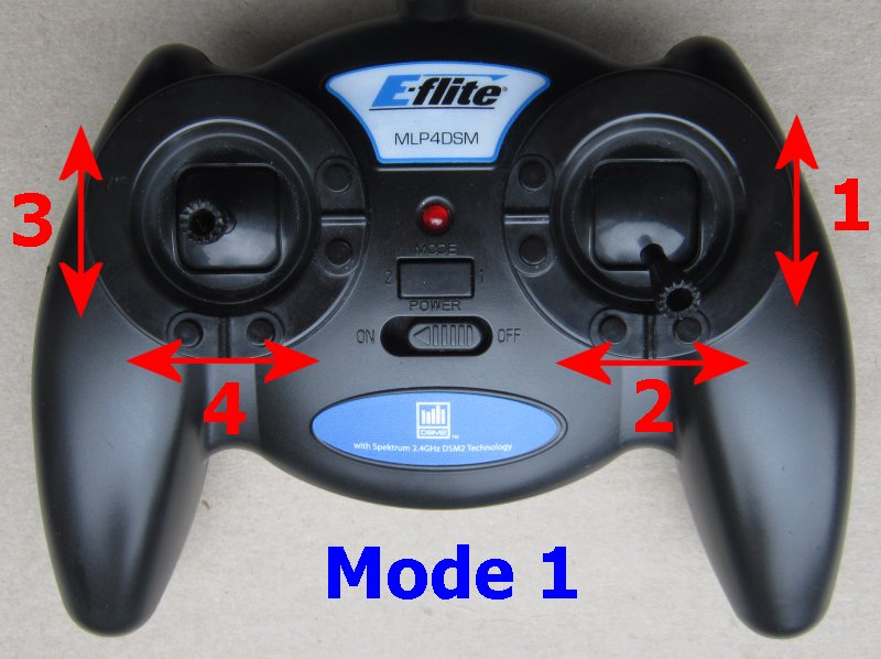
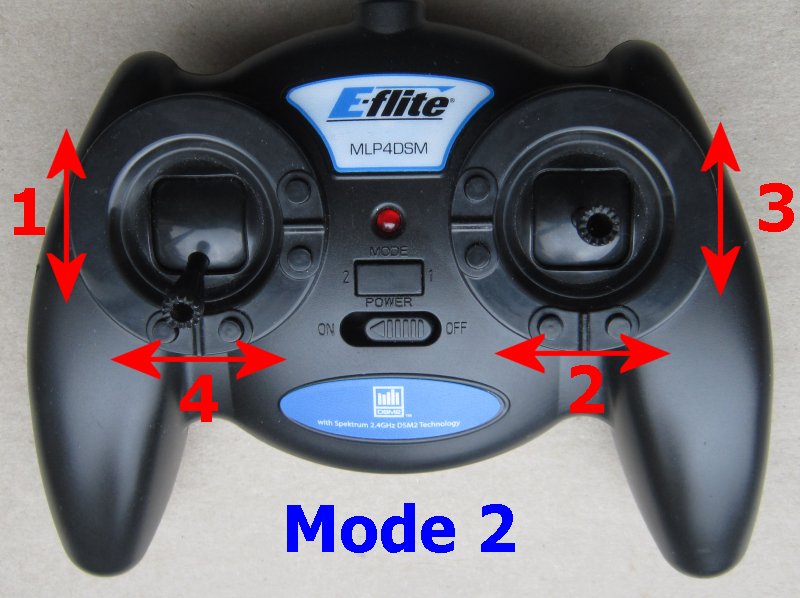
1. Switch Transmitter on.
2. Ch3 (Elevator) should be normal, not reversed.
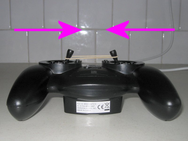
3. Hold left/right sticks (Ch2/4) in towards middle of Tx (use rubber band if necessary).
4. Switch Receiver on and wait for the Led to flicker very fast.
5. Center all sticks.
Make choices:
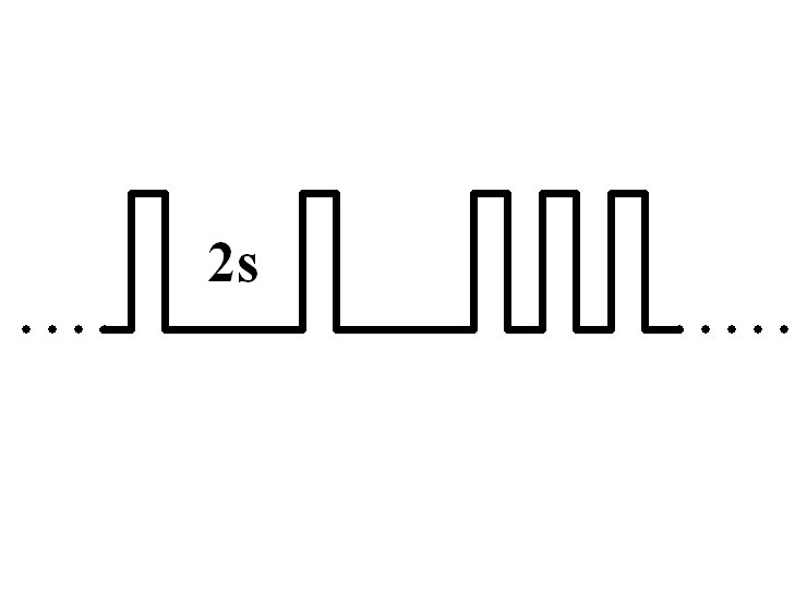
6. The led flashes the setting for the first 'Level' (eg: 1-flash = Motor output 'H').
7. Yes = push the Ch3 (Elevator) stick forward (to top of Tx) to accept this option and advance to next Level.
8. No = pull the Ch3 (Elevator) stick back (to bottom of Tx) to see next option for same Level.
9. Continue through all Levels until Led comes on solid.
Settings are saved automatically at the end so switch off at any time to abort.
Say 'yes' to every item to just see what is currently set.
|
Changing 'P2' from Ch4 to Ch5. Level 1: 3-flash = P Level 2: 2-flash = P2 Level 3: 1-flash = Servo Level 4: 5-flash = Ch5 |
4. DX3:
1. Use full 'brake' to make receiver enter programming mode on startup.
2. Use 3-position Aux channel to make yes/no choices.