
|
|
Rx65-6 Instructions (v610)
|
|
|
|
1. DEFAULT SETUP
|
Item |
Setting | Details |
|
Purpose: |
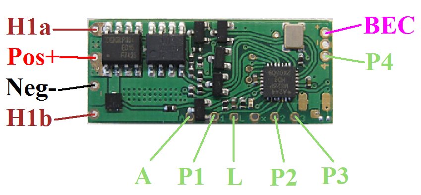
Rx65-6 |
Boat with joystick transmitter |
|
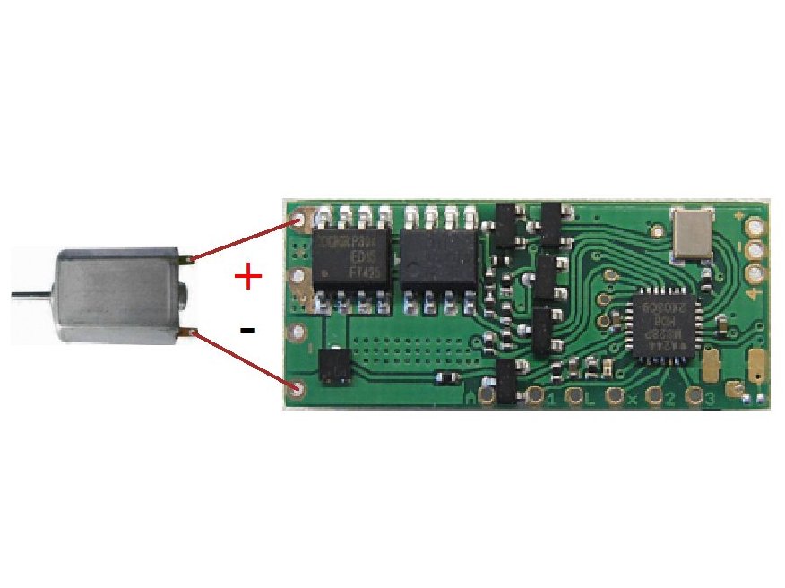
Red wire positive (+) Black wire negative (-) |
Battery |
3-18v Observe polarities |
|
H1 output Brown wires |
Motor Ch3 (Elevator) |
Integrated forward/reverse ESC for brushed motors Center off |
|
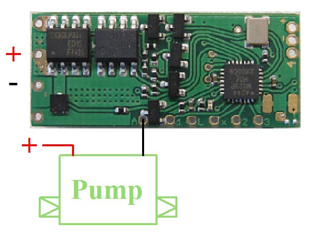
P1/A output |
On/Off switch (Ch1) |
Water pump, radar, searchlight, etc. 2A max using 'A' pad Ch1 used as latching on/off switch Move stick up and center to toggle on/off |
|
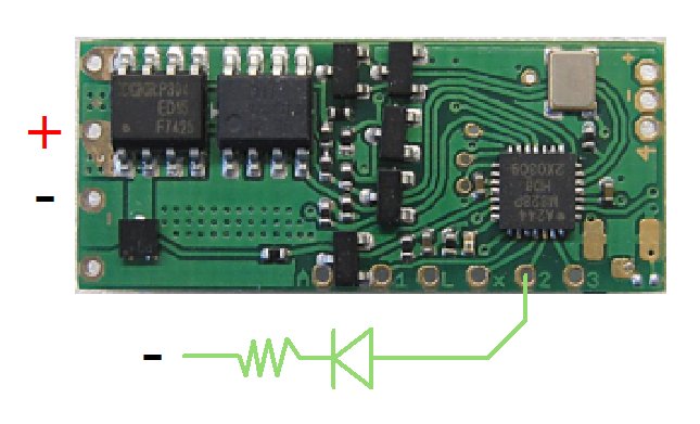
P2 output |
Lights (Ch1) |
Led needs current limiting resistor Ch1 used as latching on/off switch Move stick down and center to toggle on/off |
|
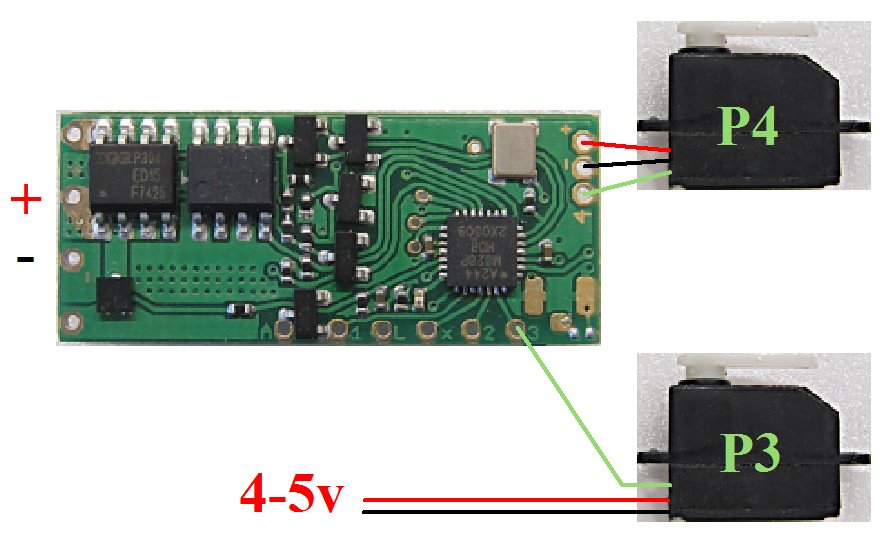
P3 output |
Servo Ch2 (Aileron) |
Standard servo (eg: sail winch) Servo may need separate 4-6v power supply (UBEC) |
|
P4 output |
Servo Ch4 (Rudder) |
Standard servo (eg: steering) Servo current should be <500mA if powered by on-board 3.3v BEC |
|
L input |
Auto-detect |
Monitors single cell lipo when used with a voltage booster |
|
Arming: |
Enabled |
Ch3 to center position (off) |
| LVC | Enabled |
LVC=Low Voltage Cutoff Led 5-flash if triggered Stop and charge battery |
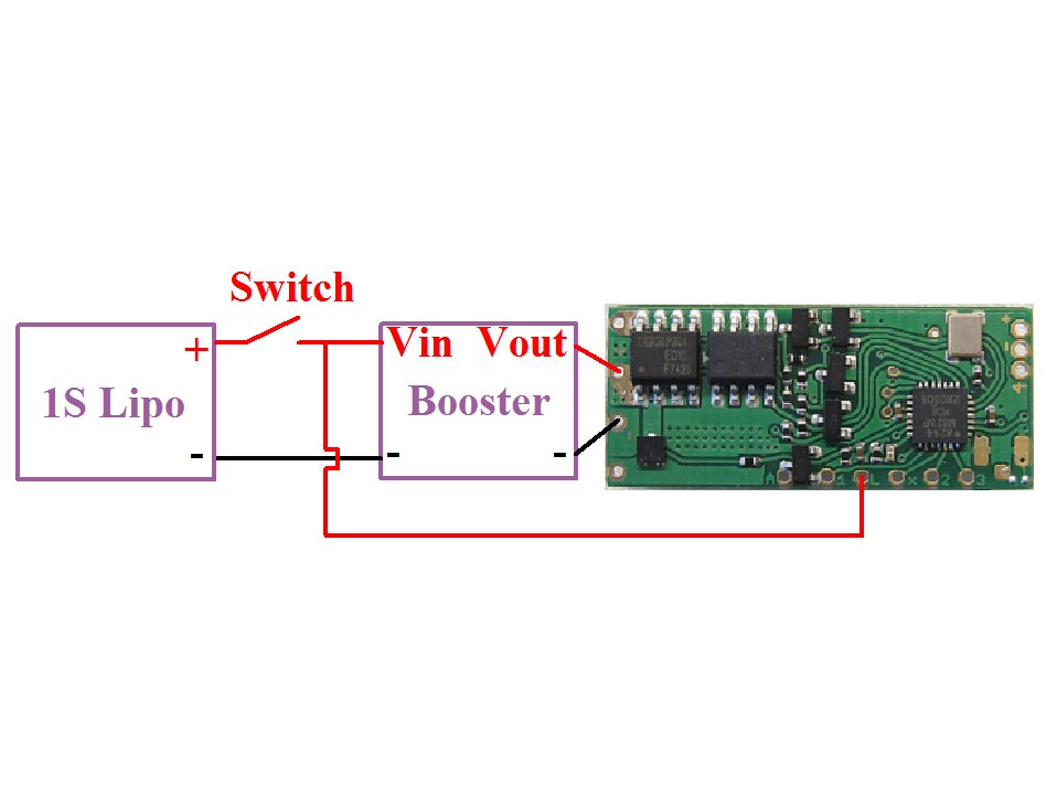
2. EXAMPLE CONNECTIONS:
|
|
|
|
|
|
'P' outputs are 3v when on and 0v when off. Led's need resistors to limit current to 20mA but high brightness led's allow a lower current (eg: 2-5mA). Google will reveal how to select resistor values but 220-470ohms will be safe starting values.
P1 controls the 'A' output. The A output is used to drive higher current things. It is 0v when on and disconnected (floating) when off. The load is normally connected permanently to positive and the A output provides a path to ground to switch it on. The A output is rated at 2A.
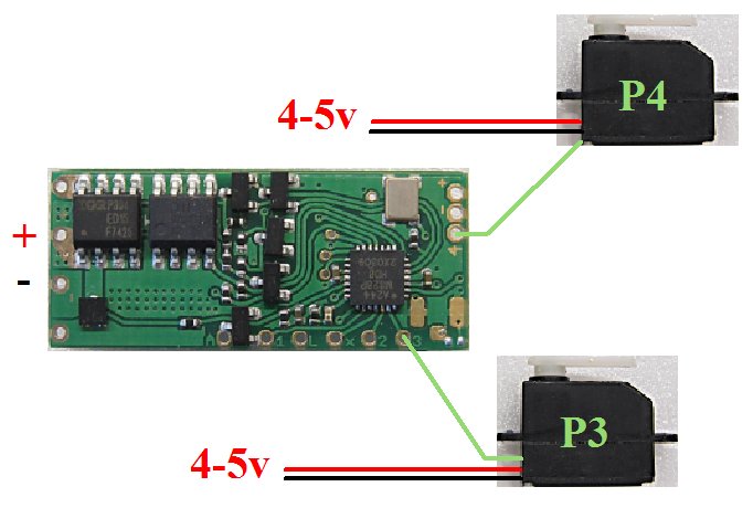
The on-board BEC may be able to power a small servo through the 3.3v BEC output (see Option 1 above). If the servo does not work properly then it needs a separate power supply (see Option 2). In this case only the signal wire must be connected to the P4 output and the servo must get a suitable voltage direct from the battery (up to 6v usually) or a UBEC device (reduces higher voltages to 5v).
The 'L' pad is intended to monitor a single cell lipo when used with a voltage booster. This allows the receiver and motor to be powered with a boosted voltage and benefit from the convenience of a single lipo. The receiver will auto-detect when a lipo is connected. It will cut power to the motor when the voltage falls to 3v (LVC). The L pad is not intended for use when powering a receiver direct from a single lipo.
3. BINDING
Bind once (not necessary if Rx was supplied pre-bound):
1. Switch Rx on and wait ~20s until led flickers fast.
2. Switch Tx on in bind mode.
3. Rx led should flash slowly; wait for it to go solid.
Change distance between Tx/Rx if binding does not work.
4. LED:
Led On = perfect reception (real-time indicator).
1 flash = Scanning (~2sec between flashes; no signal or not bound if never stops).
5 flash = LVC/Brownout (voltage went too low; check battery/motor load).
5. FAILSAFE:
The motor output is not active on startup and while scanning for a signal.
The motor output 'holds' last known settings on short signal losses (<1sec) and then slows to a stop over 3 seconds.
6. CHANGING SETTINGS:
The following changes can be made by simply shorting two pads together (eg: with a paperclip):
1. Perform a 'Hard reset' (factory reset).
2. Change motor control between 'low off' and 'center off'.
3. Enable/disable LVC (eg: when using Nicads, NiHMs, LiFe cells).
4. Enable/disable Selecta.
5. Enable/disable Cruise Control/Failsafe.
'Paperclip' changes
This receiver has many other options that are described on the features page.
These are changed using a technique called 'programming': v610.