
|
|
DT Transmitter - Tx1 Instructions - v1.1.4
|
|
Select the appropriate model number (1-4) and switch Tx1 off.
Switch the target Rx on in bind mode.
If the joystick is being pressed IN when power is applied (or bind plug on Pin1), Tx1 will enter Bind mode.
The LED flashes twice a second for ~5s while binding.
Bind is complete when the Rx LED comes on solid.
Tx1 has the following modes of operation:
1. PPM module with JR pulse order (TAER567).
2. PPM module with Futaba pulse order (AETR567).
3. PPM module with Multiplex aeroplane pulse order (AERT567).
4. PPM module with Multiplex heli pulse order (AERCT67).
5. PPM module with Multiplex modified pulse order (plane Ch3/5 swop).
6. 2ch with one-direction throttle (default).
7. 2ch with two-direction throttle (centre off).
8. 2ch with two-direction throttle (centre off) with auto-close.
The LED will flash the model number on startup (1-4 flashes).
In modes 1-5, the led will come on solid when transmitting.
In modes 6-8, the led will come on but flicker when transmitting.
Tx1 is supplied set to mode 6.
To operate in this mode it needs Push-buttons or Bind plug on the signal pins.
Tx1-J comes with a joystick that is a 5-way switch like used in mobile/cell phones.
Tx1 always transmits 7 channels but in modes 6-8 channels 3-7 are at neutral.
A 130mA 1S lipo it should last several hours but charge regularly to avoid damage.
2.1 CHANNEL 1:
UP and DOWN (P4/P2) opens and closes the Throttle.
IN (P1) cuts the Throttle quickly.
Throttle is off on startup.
In modes 6 & 7 the throttle stays where you move it to.
In mode 8 the throttle closes itself when you release the button/remove plug.
In mode 8, mid-stick/center is off.
Brief presses make small changes; continuous/longer presses make bigger changes.
2.2 CHANNEL 2:
LEFT and RIGHT controls the Rudder/Steering.
Rudder is deflected only while the joystick is pressed.
The time taken to reach full throw can be set to four speeds.
The rudder centers automatically at double the chosen speed (faster).
Partial throws are achieved by short presses and pulsing the joystick.
Servo throws can be set to 64%, 100% or 136%.
The direction of travel can be reversed.
Please note that Ch2 will normally be used as a Rudder so that term in used in these instructions. The actual channel that is being controlled is the Aileron channel.
Tx1 settings are changed by holding the Joystick in the direction described below as power is applied. A bind plug on the indicated Pin can be used instead.
Settings are specific to model numbers so select the correct model before changes.
These settings are only relevant to Modes 6-8.
The LED will flash the current setting twice (eg: 3-flash (twice) for option 3).
If the Joystick continues to be held (or the bind plug remains in place) after the two sets of flashes, the option number will increment or wrap (eg: 2 becomes 3).
Whatever option is flashing at the time the Joystick is released (or bind plug removed) will be saved.
2.3.1 MODEL NUMBER:
If the joystick is being pressed UP when power is applied (or bind plug on Pin4), the model number can be changed.
1 to 4 flashes = model number (default 1).
2.3.2 RUDDER REVERSE:
If the joystick is being pressed LEFT when power is applied (or bind plug on Pin3), the Rudder can be reversed.
1-flash = normal direction (default)
2-flash = reversed.
2.3.3 RUDDER THROWS:
If the joystick is being pressed RIGHT when power is applied (or bind plug on Pin5), the Rudder throw can be changed.
1-flash = 64% (default)
2-flash = 100%
3-flash = 136%.
2.3.4 RUDDER SPEED / RATE OF CHANGE:
If the joystick is being pressed DOWN when power is applied (or bind plug on Pin2), the time taken for Rudder to move from center to full throw can be changed.
1-flash = very slow (default)
2-flash = slow
3-flash = faster
4-flash = very fast
2.3.5 THROTTLE SPEED / RATE OF CHANGE:
If there is a bind plug on Pin7 when power is applied, the time taken for Throttle to move from minimum to maximum can be changed.
This feature can only be changed in Modes 6-8.
1-flash = very slow (default)
2-flash = slow
3-flash = faster
4-flash = very fast
Certain DT receivers have a special programming mode for changing settings over radio link (eg: Dual-motor, Car, DSM2ir, etc).
For those receivers to enter programming mode, the Rudder and Aileron sticks have to be 'pinched' in towards the middle when the Rx locks first onto a signal. Tx1 can be made to simulate this if Pin1 and Pin7 have bind plugs on them when power is applied to Tx1.
As soon as the led on the DT Rx comes on flickering very fast, it has entered programming mode. The bind plug on Tx1 Pin7 has to be removed to proceed with programming the DT Rx. The plug on Pin1 should be removed as well.
DT Rx programming options are changed or accepted using the Elevator stick. Once Pin7 & 1 have been removed from Tx1, the UP/DOWN buttons (or Pins 4/2) operate the elevator channel (instead of Throttle).
The DOWN direction (or a bind plug on Pin2) says 'no' to a DT Rx option.
The UP direction (or a bind plug on Pin4) says 'yes' to a DT Rx option.
As soon as the last DT Rx programming option has been accepted, its led will come on solid as it still has a signal from Tx1.
Tx1 does not know when DT Rx programming is complete. So Tx1 has to be switched off to end this special mode. When switched back on and the DT Rx locks onto the signal again, Tx1 will have normal control.
Tx1 is supplied set to Mode 6 (2ch). You should get it working in this mode first.
To operate as a module, change to Mode 1-5 and apply PPM signal to Pin7.
The host transmitter can have 4 or more channels but only the first 7 are used.
5 pulse orders are supported (JR, Futaba and 3 for Multiplex).
Pin7 'floats' so needs active/strong highs and lows.
The input can idle high or low.
3.1 PPM CHANNEL ORDER
If there is a bind plug on Pin6 when power is applied, the expected channel order can be changed:
1-flash = TAER (JR)
2-flash = AETR (Futaba)
3-flash = AERT (Multiplex plane)
4-flash = AERCT (Multiplex heli)
5-flash = same as Mode3 but Ch3/5 swopped (allows use of 4ch receivers with Aileron2/Elevon2 mixing)
TAER= Throttle, Aileron, Elevator, Rudder, Ch5, Ch6, Ch7.
AETR=Aileron, Elevator, Throttle, Rudder, Ch5, Ch6, Ch7.
AERT=Aileron, Elevator, Rudder, Throttle, Ch5, Ch6, Ch7.
AERCT=Aileron(Roll/Ch2), Elevator(Pitch/Nick/Ch3), Rudder(Yaw/Ch4), Collective(Ch5), Throttle(Ch1), Ch6, Ch7.
3.2 BINDING
Binding should be as described in section 1.1 but the PPM signal can prevent it from entering bind mode and make it go into the special mode for programming DT receivers (section 2.4). The work-around is to try again, or to bind without PPM connected (not active). In orther words, Pin7 must be high when Pin1 is low to enter bind mode.
| MODE Pulse |
1 Tx1 with JR |
2 Tx1 with Futaba |
3 Tx1 with MPX Plane |
4 Tx1 with MPX Heli |
5 Tx1 with MPX Plane Ch3/5 swop |
|---|---|---|---|---|---|
| Pulse 1 | Channel 1 | Channel 2 | Channel 2 | Channel 2 | Channel 2 |
| Pulse 2 | Channel 2 | Channel 3 | Channel 3 | Channel 3 | Channel 5 |
| Pulse 3 | Channel 3 | Channel 1 | Channel 4 | Channel 4 | Channel 4 |
| Pulse 4 | Channel 4 | Channel 4 | Channel 1 | Channel 5 | Channel 1 |
| Pulse 5 | Channel 5 | Channel 5 | Channel 5 | Channel 1 | Channel 3 |
| Pulse 6 | Channel 6 | Channel 6 | Channel 6 | Channel 6 | Channel 6 |
| Pulse 7 | Channel 7 | Channel 7 | Channel 7 | Channel 7 | Channel 7 |
| Pulse 8+ | Not used | Not used | Not used | Not used | Not used |
Tx1 can be powered by 3.2-10v although a 3.3-6v supply is recommended.
Tx1 operates at 3.1v with an on-board regulator. So the ideal PPM input to the signal Pin7 is 3.1v but can range from 2.1 to 3.6v (max). Input low range is 0 to 0.8v.
Pin7 'floats' so needs active/strong highs and lows.
|
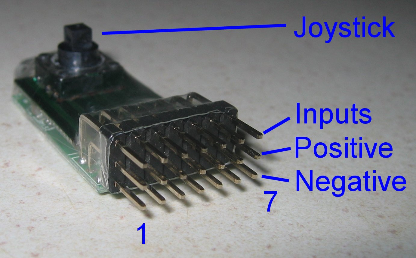
4.2 PIN CONNECTIONS:
A bind plug or any external normally open switches can be used to achieve the same results as the joystick in the J version.
Any circuit that can produce a PPM stream can be used to feed channel position data to Tx1 (eg: this could be used to feed analogue (pot) stick positions).
| Pin number | Normal usage | Startup |
|---|---|---|
| Pin1 | IN (throttle cut) | Bind |
| Pin2 | DOWN throttle | Joystick rudder speed |
| Pin3 | LEFT rudder | Joystick rudder reverse |
| Pin4 | UP throttle | Model number |
| Pin5 | RIGHT rudder | Joystick rudder throws |
| Pin6 | - | Mode /PPM pulse order |
| Pin7 | PPM input | Joystick throttle speed |
| Pin1+7 | - | Joystick DT Rx programming mode |