
|
|
Tx1-K1 Instructions - v1.0.1
|
|
|
|
PRODUCT: Tx1-K1
VERSION: 1.0.1
1. DESCRIPTION:
Tx1-K1 is a 2.4GHz DSM2-compatible transmitter module intended to be controlled with a PC or microprocessor.
It transmits twice every 22ms. It transmits 7 channels with 10bit channel position data.
It requires a serial data feed and it only transmits when that is present.
2. PRECAUTIONS:
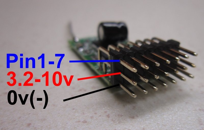
Tx1-K1 operates at 3.1v and requires at least 3.2v to operate it. The maximum allowed power supply voltage is 10v.
The voltage applied to Pins 1, 2, 3 and 8 must not exceed 3.6v. Zener diodes and/or resistors may be required (see above).
Pins 4-7 are rated at 10mA for driving leds so current limiting resistors may be needed (180ohms exist on each output).
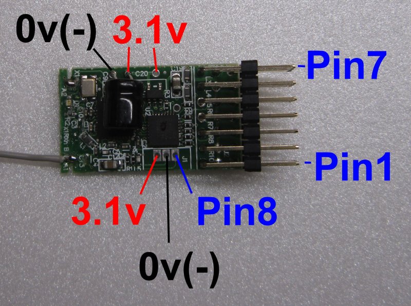
3. PIN CONNECTIONS:
Pin 1 - Bind
Pins 2-3 - Model number selection
Pins 4-7 -Outputs to drive leds to indicate model number
Pin8 - Serial input
4. LED:
The transmitter's led flickers fast when no valid serial input is present.
The led stays on solid and is transmitting when there is a valid serial input.
5. MODEL NUMBER:
A unique relationship is created between the Tx and Rx during binding. Tx1-K1 can create 4 such relationships referred to here as 'model numbers'.
The active model is based on the current state of Pins 2 and 3 (ie: they are not 'remembered').
Only one model number is active at any time but the model can be changed at any time.
Model 1 - Pin 2 low, Pin 3 low
Model 2 - Pin 2 low, Pin 3 high
Model 3 - Pin2 high, Pin 3 low
Model 4 - Pin2 high, Pin3 high (default)
The pins have internal pullups and idle high. So Model 4 is the default if Pins 2 and 3 are left floating.
Connect Pins 2 and/or 3 to ground (-) to make then low.
Pins 4-7 reveal the current Model number selected. Connect led's between the 'signal' pin and ground (-).
6. BINDING:
Pin1 has an internal pullup and should normally be held high or left floating. To enter bind mode:
1. Select the appropriate model number as described above.
2. Hold Pin 1 low for ~2 seconds to enter bind mode and then make high/floating again.
3. The Tx1 led will flash for ~5 seconds. Bind is complete as soon as the led comes on solid or flickering fast.
7. SERIAL INPUT:
The transmitter will only transmit with a valid serial input on Pin 8.
It will stop transmitting ~2 seconds after the serial input stops.
It will start/restart automatically.
It always transmits the most recent data received.
Pin 8 'floats' so requires active/strong highs and lows.
The required serial payload is 16 bytes RS-232 at 115200 baud, 8 bit, no parity, at least 1 stop bit, LSB first. It is expected every 22ms but timing is not critical.
Byte 1 - Checksum (sum of bytes 2-16 cast to 1 byte)
Byte 2 - Not used (can be any value)
Bytes 3-16 - 2 bytes per channel with following structure 0b000 CCC 9876543210
- 000 = not used (normally zeros)
- CCC = channel number (0=Thr, 1=Ail, 2=Ele, 3=Rud, 4=Gear, 5=Aux1, 6=Aux2)
- 9876543210 = 10bit channel position
(eg: byte 3 is 0b000CCC98 and byte 4 is 0b76543210, bytes 5 and 6 are the next pair, etc.)
DT receivers with a serial output can be used to provide an input to Tx1 for testing.