|
|
Tx2 - v207 Instructions
|
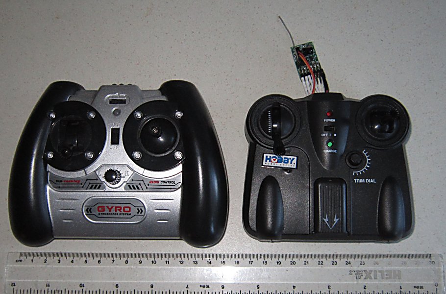
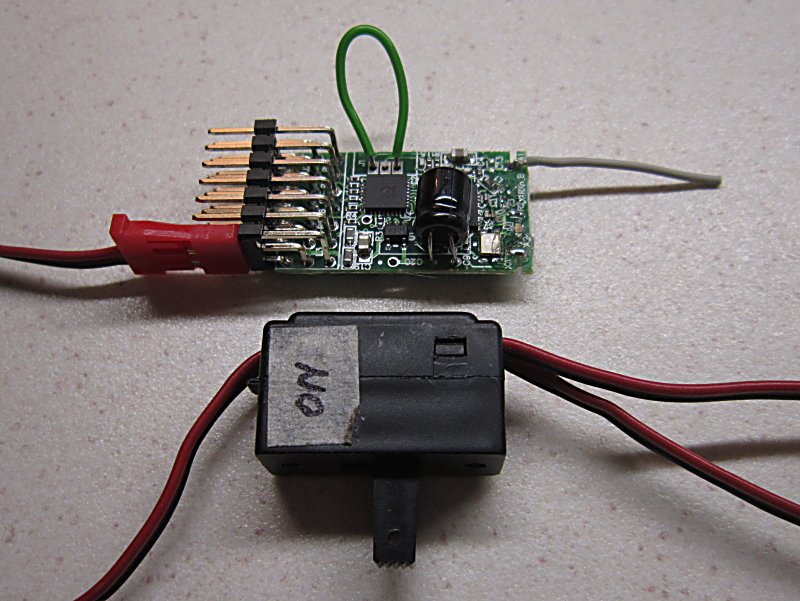
Tx2 is a reprogrammed receiver which is used to make a 2.4GHz transmitter compatible with other DSM2 receivers.
It has 7 'profiles' to help you find the most suitable for your needs.
|
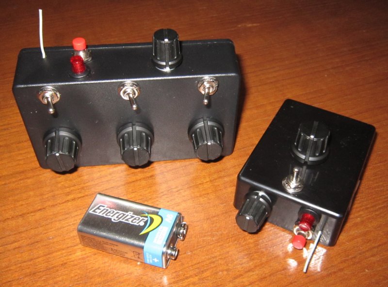
EXAMPLE: Tx21, Tx22 and Tx23 are controllers for trains using Profile 1 and Profile 3 of Tx2. Controls for Speed, Direction, Inertia, Lights. |
|
EXAMPLE: Coax heli and cheap plane transmitters Proportional or switched control of up to 7 channels |
PRODUCT: Tx2
GENERAL INFORMATION:
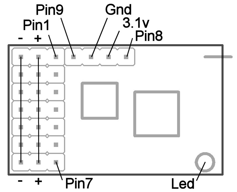
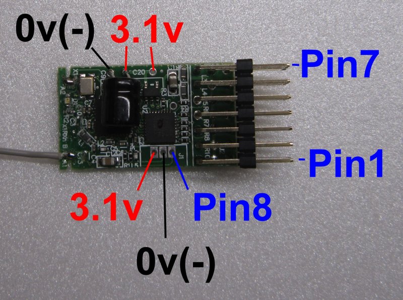 (3.1v is source for Vref) |
 (1-2S lipo or 3-6 AA or 9v PP3) |
 |
 |
PROFILES:
Seven profiles are available to better suit different needs:
Control Pin |
PROFILE 1 Trains (Tx22/Tx24) |
PROFILE 2 Conventional (5ch) |
PROFILE 3 Trains (Tx23) |
PROFILE 4 Conventional (7ch) |
PROFILE 5 Trains (Tx20) |
PROFILE 6 Trains (Tx21) |
PROFILE 7 Simple 7ch (Tx27) |
|---|---|---|---|---|---|---|---|
| Pin1 | Ch1 + Ch6 analogue | Ch1 + Ch6 analogue | Ch1 analogue | Ch1 analogue | Ch1 + Ch6 analogue | Ch1 + Ch6 analogue | Ch1 analogue |
| Pin2 | Ch2 analogue | Ch2 analogue | Ch2 analogue | Ch2 analogue | Ch2 digital (mid/low) | Ch2 digital (mid/low) | Ch2 analogue |
| Pin3 | Ch3 analogue | Ch3 analogue | Ch3 analogue | Ch3 analogue | Ch3 analogue | Ch3 analogue | Ch3 analogue |
| Pin4 | Ch4 digital (mid/low) | Ch4 analogue | Inertia analogue | Ch4 analogue | Ch4 digital (mid/low) | Ch4 digital (mid/low) | Ch4 analogue |
| Pin5 | Ch5 digital (high/low) + BIND | Ch5 digital (high/low) + BIND | Ch5 analogue + BIND | Ch5 analogue + BIND/REVERSE | Ch5 digital (high/low) + BIND | Ch5 digital (high/low) + BIND | Ch5 analogue + BIND |
| Pin6 | Inertia (or Ch4/5 analogue) |
REVERSE | Ch6 analogue | Ch6 analogue | - | Inertia (or Ch4/5 analogue) |
Ch6 analogue |
| Pin7 | Ch7 analogue | TRIM | Ch7 analogue | Ch7 analogue + TRIM | Ch7 analogue | Ch7 analogue | Ch7 analogue |
| LED on PCB | LED1 output | LED1 output | LED1 output | LED1 output | LED1 output | LED1 output | LED1 output |
| Pin8 | LED2 output + PROFILE | LED2 output + PROFILE | LED2 output + PROFILE | LED2 output + PROFILE | LED2 output + PROFILE | LED2 output + PROFILE | LED2 output + PROFILE |
ANALOGUE INPUTS:
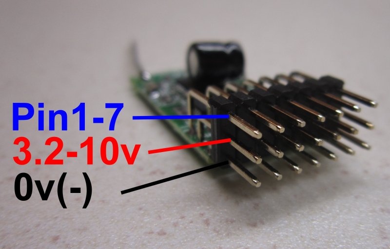
Pins 1-7 are used as inputs to control Channels 1-7 or other functions.
Analogue inputs are 'fully adjustable' (proportional) and can have up to 1024 positions.
This is achieved by adjusting the voltage applied to the Pin with a pot or switch with resistors.
Channel positions will be random if analogue pins are left 'floating' (unconnected).
Profiles with Inertia must have a pot connected to that input (or be grounded) to avoid random behaviour on Ch1 (Throttle).
It is also common for floating inputs to 'follow' another channel (instead of being random).
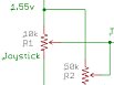
REFERENCE VOLTAGE:
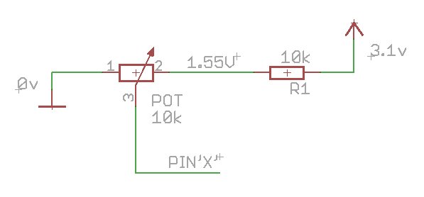
To give predictable results, the voltage applied to an analogue input needs to be proportional to a 'reference voltage' which is known to give full scale measurements. Tx2 is powered through an on-board 3.1v voltage regulator. This is too high to use directly as the reference voltage. However, it is easy to create a 50% voltage with 2 equal resistors. So this principle is used to create a 1.55v reference (3.1 / 2 = 1.55v).
Analogue inputs therefore normally need to have components to adjust voltage between 0 and 1.55v (eg: with a 10k pot), and another resistor of equal value (eg: 10k) to halve the 3.1v Vref. Pots and resistors can be any equal value between 4k7 and 100k but 10k for both is a common choice (10k = 10 000 ohms).
DIGITAL INPUTS:
Some inputs are classed as 'digital' which means the Pin can only have two states, High or Low.
The state will be High when the Pin is over 2.1v (eg: 3.1v). The state will be Low when the Pin is below 0.8v (eg: 0v).
When nothing is connected to digital inputs, internal resistors pull them up to 3.1v (High).
When a Digital Pin is High it makes the channel go either to a 'high' channel position (eg: 2.1ms) or a 'middle' position (eg: 1.5ms).
When a Digital Pin is Low it makes the channel go to its 'low' position (eg: 0.9ms) in all profiles.
THROWS:
Tx2 uses 10bit resolution. This means channels have 1024 positions.
150% throws: 0-1.55v = 0-1023 = 0.9-2.1ms servo pulse.
100% throws: 0-1.55v = 171-852 = 1.1-1.9ms servo pulse.
THROW OPTIONS:
1: Pin1 (motor) 100% and Pins2-7 150% (default).
2: Pins1-7 150%.
3: Pins1-7 100%.
LED:
If Tx2 is built into a box, Pin8 can drive an external 'LED2'.
The Led on Tx2 ('LED1') switches itself off after 1 minute to save power.
MAXIMUM VOLTAGES:
PIN 1-8 Analogue input: 0-1.55v.
PIN 1-8 Digital input: 0v or 3.1v.
PIN 1-8 Max input: 3.6v.
Battery: 3.2-10v.
Low voltage protection: None.
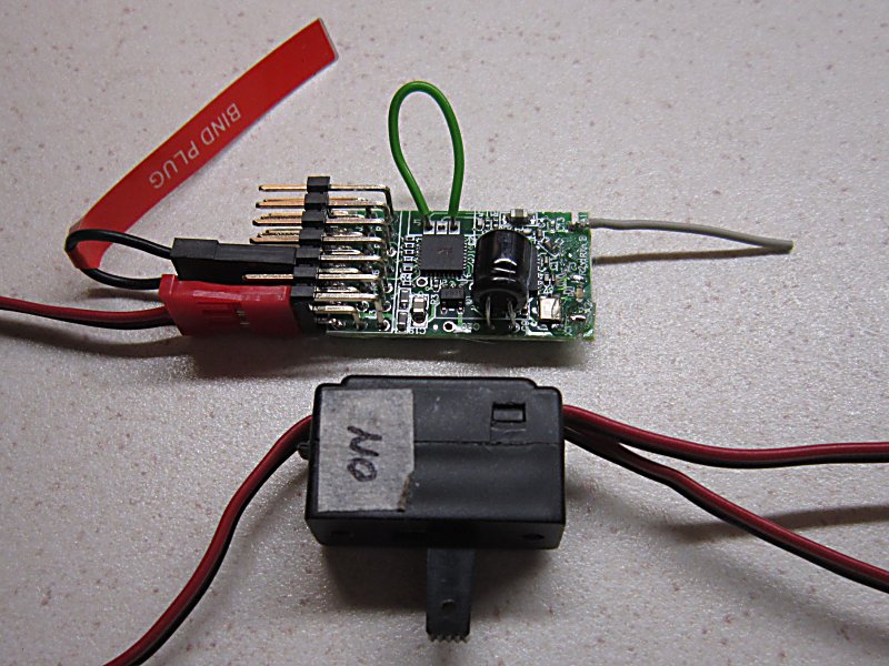
BIND:
Receivers have to be bound to Tx2 for them to accept its signals:
1. Get the receiver into bind mode (led flashing fast).
2. Press and hold the BIND button, switch Tx2 on and then release the BIND button.
3. The Led will flash slowly for a few seconds.
TRIMS:
Trims change in steps of 4 and can shift the entire range without restriction.
One button is used to change trims of any channel:
1. Move joystick/pot/switch to 'center' position (0.8v).
2. Press and hold TRIM button and the Led will go off.
3. Move joystick/pot/switch 'full throw' in direction required for trim change (0v or 1.55v).
4. Led will flash and Trim will change '1 click' per half second.
5. Trims have 128 'clicks' each way and the Led will stay on for 2 seconds when the trim value returns to center.
6. Release TRIM button to save.
Separate trim pots can also be used with each channel. See 'trim pot' section below.
REVERSE:
One button is used to reverse any channel:
1. Move joystick/pot/switch to 'center' position (0.8v).
2. Press and hold REVERSE button and the Led will go off.
3. Move joystick/pot/switch to 'full UP' (1.55v) and the channel will change to NORMAL direction immediately.
4. Move joystick/pot/switch to 'full DOWN' (0v) and the channel will change to REVERSE direction immediately.
5. Release REVERSE button to save.
PROFILE:
Pin8 is used to change the Profile.
You will normally set this before doing anything else and never change it again.
1. Make sure Pin5 has nothing connected (Pin5 floating or at 3.1v).
2. Connect Pin8 to 3.1v (Pin8 = 3.1v).
3. Apply power to Tx2.
4. LED1 will flash the current Profile twice
5. While Pin8 continues to be 3.1v, the LED will scroll through the options.
6. Release Pin8 to save.
7. Switch Tx2 off when the led stays on.
THROWS:
Pins 5 and 8 are used to change Throw options.
1. Place the Bind plug on Pin5 or press Bind button (Pin5 = 0v).
2. Connect Pin8 to 3.1v (Pin8 = 3.1v).
3. Apply power to Tx2.
4. LED1 will flash the current Throws option twice
5. While Pin5 continues to be 0v, the LED will scroll through the options.
6. Release Pin5 to save (Pin5 floating).
7. Switch Tx2 off when the led stays on.
TRAIN FEATURES:
'MOTOR' CHANNEL:
The motor channel controls speed and uses different channel numbers to control up to 7 trains individually.
It will normally be 'center off' if the Direction feature is not used.
'DIRECTION' CHANNEL:
The direction channel will only have any effect with ESC's that require a second channel to set Fwd/Rev direction.
On Tx21 and Tx22 the Direction switch is often used for directional lights.
INERTIA / BRAKE / MOMENTUM:
The inertia control modifies the Motor channel to smooth out changes in speed.
It ranges from having no effect to making the speed ramp up/down progressively over up to 60 seconds.
The Led flickers while a transition is in progress and reducing the inertia setting while in motion has a braking effect.
The Inertia pot can be used to control Inertia, Ch4 or Ch5. The operator change change this at any time.
LIGHTS:
The Direction channel can be used to switch up to 4 lights on and off with DT receivers.
The Bind button can be used to switch up to 2 lights on and off DT receivers.
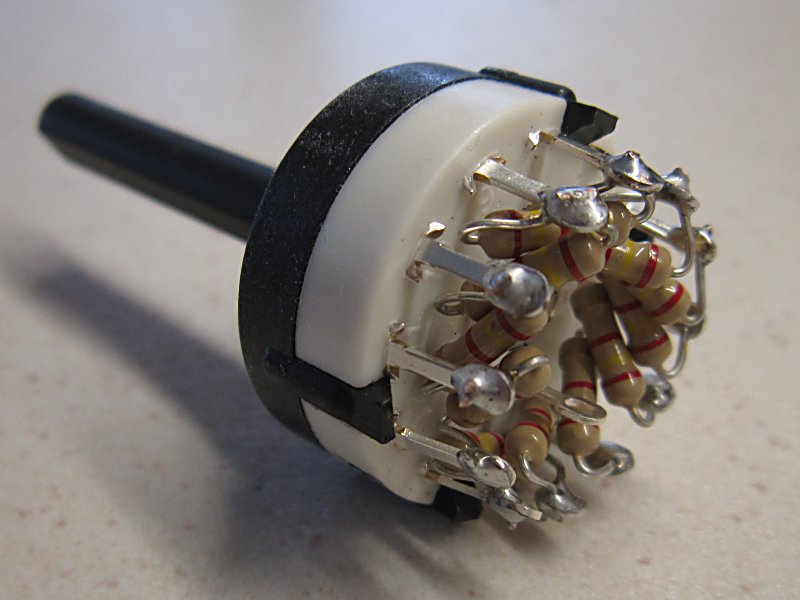
LOCO SELECTION:
Rx6x receivers have a 'Selecta' feature which allows locos to be brought in and out of service without touching them.
Tc22 has a 12-way switch to allow up to 12 locos to be controlled at the same time.
COUPLING:
Several channels can be used to control a servo to operate a coupling.
PROFILE 1:
Profile 1 is intended for trains.
Profile 1 is used in Tx22 and Tx24.
| Control Pin |
Function |
|---|---|
| Pin1 | Ch1 + Ch6 analogue (Motor) |
| Pin2 | Ch2 analogue |
| Pin3 | Ch3 analogue (Direction) |
| Pin4 | Ch4 digital (mid/low) |
| Pin5 | BIND + Ch5 digital |
| Pin6 | Inertia, Ch4 or Ch5 (analogue) |
| Pin7 | Ch7 analogue |
| LED on PCB | LED1 output |
| Pin8 | LED2 output + PROFILE |
WIRING DIAGRAM:
Tx22 circuit
Tx24 circuit
1 train controller with switches for Direction and Ch2
1 train controller with switch for Direction (Tx21)
1 train controller with pot for Direction
PIN 1:
Pin1 is expected to control motor speed using Channel 1 or Channel 6.
Changes are smoothed by the Inertia feature.
PIN 2:
Pin2 is used to control the Selecta feature in Tx22 using Channel 2.
Alternatively, Ch2 is a spare channel for any purpose.
PIN 3:
Pin3 is expected to control 'motor direction' using Channel 3 on receivers/ESCs that use a separate Direction channel.
Alternatively, Ch3 is a spare channel which is often used for lights with Tx22.
PIN 4:
Pin4 is digital and has an internal pullup and is used to control Channel 4.
It is at its mid position when high (button released) or low position (button pressed).
PIN 5:
Pin5 is digital and has an internal pullup.
It requires a pushbutton switch or bind plug to pull down to 0v.
The Transmitter will enter Bind mode if the Bind button is being pressed when Tx2 is switched on.
The Bind button can be used to toggle Ch5 in normal use for lights, servo etc.
It is also used to calibrate Ch1, Ch2 and Ch7 (see below).
PIN 6:
By default, Pin6 controls Inertia. It modifies the Ch1 position and is not used for Ch6.
Pin6 must be grounded or have a pot installed to avoid random Ch1 behaviour.
The Inertia pot can be used to control Inertia, Ch4 or Ch5. The operator change change this at any time (see below).
PIN 7:
Pin7 is analogue and requires a pot or switch with resistors to control its value.
PIN 1, PIN 2 and PIN7 CALIBRATION:
Tx22 has a Throttle pot that has a 'click' at the center position. When Throttle is used 'center off' it needs to be calibrated so that it centers accurately to make the 'click' match the 'off' position in the receiver. Tx22 uses Ch2 for a 12-way Selecta switch. Pin7 can also have a 12-way switch. These three channels can be calibrated so they generate the same values on all units. Calibration is done using the Bind button while Tx22 is on. Calibration has to be started within 1 minute of switching the transmitter on. Calibration normally only needs to be done once.
1. Center the Motor pot.
2. On Tx22 put the 12-way Selecta switch in the 6 o'clock position (assuming 1 o'clock is fully CCW).
3. Do the same for Pin7 if it has a 12-way switch.
4. Switch the Tx on. Within 60s, press and hold the Bind button.
5. After ~20s the Led will go out for 2s and come on for 3s. Release in this time to only calibrate Ch1.
6. After ~25s the Led will go out for 2s and come on for 3s. Release in this time to only calibrate Ch1+2.
7. After ~30s the led will go off and stay off until you release the Bind button. This calibrates Ch1+2+7.
INERTIA or CH4/CH5 choice:
The Pin6 pot can be used to control Inertia or Ch4 or Ch5. Only one function can be active at any time. Each time the procedure is followed the function will toggle between [Inertia] and [Ch4 or Ch5].
The Bind button is used as follows:
* If the Bind button is being pressed when the Tx is switched on, the Tx will enter Bind mode.
* If the Bind button is pressed for less than 20s at any time, it will normally control Ch5 (see notes below).
* If the Bind button is pressed for 20s or more within the first 60s of switching the Tx on, it will perform calibration.
* If the Bind button is pressed for 20s or more after the first 60s of switching the Tx on, it will toggle what the Inertia pot is used for.
To toggle what the Inertia pot is used for:
1. Switch the Tx on and wait more than 60s.
2. Press and hold the Bind button.
3. After ~20s the Led will go out for 2s and then come on for 3s. Release in this time to select Ch4.
4. After ~25s the Led will go off and stay off until you release the Bind button. This selects Ch5.
5. Repeat steps 1 to 3 to select Inertia control.
Notes:
* If the Inertia pot is being used for Inertia, the Bind button controls Ch5 when pressed for less than 20s.
* If the Inertia pot is being used for Ch5, the Bind button has no effect on Ch5 but is still used for Binding and toggling what the Inertia pot is used for.
* If the Inertia pot is being used for Ch4, Pin4 has no effect on Ch4. The Bind button controls Ch5 when pressed for less than 20s.
PROFILE 2:
Profile 2 is a simple 5 channel transmitter.
| Control Pin |
Function |
|---|---|
| Pin1 | Ch1 analogue |
| Pin2 | Ch2 analogue |
| Pin3 | Ch3 analogue |
| Pin4 | Ch4 analogue |
| Pin5 | BIND + Ch5 digital |
| Pin6 | REVERSE |
| Pin7 | TRIM |
| LED on PCB | LED1 output |
| Pin8 | LED2 output + PROFILE |
WIRING DIAGRAM:
5 channels
PINS 1-4:
Pins 1-4 are analogue and require pots to control their values.
PIN 5:
Pin5 is digital and has an internal pullup.
It requires a pushbutton switch or bind plug to pull down to 0v (=active).
It controls BIND on startup and Ch5 in normal use.
Ch5 can only be at one extreme (position 0) or the other (position 1023).
Ch5 cannot be reversed or trimmed.
PIN 6:
Pin6 is digital and has an internal pullup.
It requires a pushbutton switch or bind plug to pull down to 0v (=active).
It controls channel REVERSE.
PIN 7:
Pin7 is digital and has an internal pullup.
It requires a pushbutton switch or bind plug to pull down to 0v (=active).
It controls TRIM.
PROFILE 3:
Profile 3 is intended for trains (Tx23).
Note:
1. If you don't need to control 3 trains, you can use spare inputs to control other things.
2. The TRIM feature will normally only be used if the motor control knob needs 'centering' more accurately.
3. The PROFILE change switch will not normally be needed.
4. There is no channel REVERSE feature.
| Control Pin |
Function |
|---|---|
| Pin1 | Ch1 analogue (Motor1) |
| Pin2 | Ch2 analogue (Motor2) |
| Pin3 | Ch3 analogue (Direction1) |
| Pin4 | Inertia analogue |
| Pin5 | Ch5 analogue (Direction2) + BIND |
| Pin6 | Ch6 analogue (Motor3) |
| Pin7 | Ch7 analogue (Direction3) |
| LED on PCB | LED1 output |
| Pin8 | LED2 output + PROFILE |
WIRING DIAGRAM:
v202
v204 and higher
'MOTOR' CHANNELS:
Pins 1, 2 and 6 are used with pots to control motor speed with Channels 1, 2 and 6.
When used with conventional ESCs (forward/reverse on one channel), center is usually off.
When used with ESCs that have a separate Direction channel, full rotation controls the full power range.
Pins 1, 2 and 6 are all set to 100% with Throws Option 1.
'DIRECTION' CHANNELS:
Pins 3, 5 and 7 are used with switches to control motor direction with Channels 3, 5, and 7.
These pins are only effective with receivers/ESCs that use a separate channel for Direction.
Alternatively, they can be used to control up to 4 lights each with DT receivers (eg: center off switches as per Tx23).
PIN 4:
Pin4 controls Inertia.
Pin4 modifies the Ch1, 2 and 6 positions and is not used for Ch4.
Pin4 must be grounded or have a pot installed to avoid random Ch1/2/6 behaviour.
PIN 5:
Pin5 requires two switches:
1. A toggle switch selects Direction2 using Channel 5 (between 0.13v and 1.42v).
2. A pushbutton (or 'Bind' plug) pulls Pin5 down to 0v to set BIND.
The Transmitter will enter Bind mode if the Bind button is being pressed when Tx2 is switched on.
PIN 1, 2 and 6 CALIBRATION:
Tx23 has pots that have a 'click' at the center position. When Throttle is used 'center off' each pot needs to center accurately so that the 'click' on the Tx matches the 'off' position in the receiver. Calibration is done using the Bind button while Tx23 is on. Calibration can only be done within 60s of switching Tx2 on.
1. Center the three Motor pots.
2. Press and hold the Bind button for ~20s until the led goes off. Ch1, Ch2 and Ch6 should now be calibrated.
3. Release the Bind button.
PROFILE 4:
Profile 4 is a 7 channel transmitter.
| Control Pin |
Function |
|---|---|
| Pin1 | Ch1 analogue |
| Pin2 | Ch2 analogue |
| Pin3 | Ch3 analogue |
| Pin4 | Ch4 analogue |
| Pin5 | Ch5 analogue + BIND/REVERSE |
| Pin6 | Ch6 analogue |
| Pin7 | Ch7 analogue + TRIM |
| LED on PCB | LED1 output |
| Pin8 | LED2 output + PROFILE |
WIRING DIAGRAMS:
7ch: 7 pots
7ch: 1 motor pot and 6 switched channels
PINS 1-4 and 6:
Pins 1-4 and 6 are analogue and require pots to control their values.
PIN 5:
Pin5 requires a pot and pushbutton for BIND/REVERSE:
1. The pot controls channel 5.
2. The pushbutton pulls Pin5 down to 0v to set BIND on startup and REVERSE in normal use.
PIN 7:
Pin7 requires a pot and pushbutton if trim is required:
1. The pot controls channel 7.
2. One pushbutton pulls Pin7 down to 0v to set TRIM.
PROFILE 5:
Profile 5 is intended for trains (Tx20).
| Control Pin |
Function |
|---|---|
| Pin1 | Ch1 + Ch6 analogue (Motor) |
| Pin2 | Ch2 digital (mid/low) |
| Pin3 | Ch3 analogue (Direction) |
| Pin4 | Ch4 digital (mid/low) |
| Pin5 | Ch5 digital (high/low) + Bind |
| Pin6 | - |
| Pin7 | Ch7 analogue |
| LED on PCB | LED1 output |
| Pin8 | LED2 output + PROFILE |
WIRING DIAGRAM:
Tx20 circuit
4 function buttons
PIN 1:
Pin1 is expected to control motor speed using Channel 1 or Channel 6.
PIN 2:
Pin2 is digital and has an internal pullup and is used to control Channel 2.
It is at its mid position when high (button released) or low position (button pressed).
PIN 3:
Pin3 is expected to control 'motor direction' using Channel 3 on receivers/ESCs that use a separate Direction channel.
Alternatively, Ch3 is a spare channel which is often used for lights with Tx21/Tx22.
PIN 4:
Pin4 is digital and has an internal pullup and is used to control Channel 4.
It is at its mid position when high (button released) or low position (button pressed).
PIN 5:
Pin5 is digital and has an internal pullup.
It requires a pushbutton switch or bind plug to pull down to 0v.
The Transmitter will enter Bind mode if the Bind button is being pressed when Tx2 is switched on.
The Bind button can be used to toggle Ch5 in normal use for lights, servo etc.
It is also used to calibrate Ch1 (see below).
PIN 6:
Pin 6 is not used.
PIN 7:
Pin7 is analogue and requires a pot or switch with resistors to control its value.
PIN 1 CALIBRATION:
Tx20 has a pot that has a 'click' at the center position. When Throttle is used 'center off' it needs to center accurately so that the 'click' on the Tx matches the 'off' position in the receiver. Calibration is done using the Bind button while Tx20 is on. Calibration can only be done within 60s of switching Tx2 on.
1. Center the Motor pot.
2. Press and hold the Bind button for ~20s until the led goes off. Ch1 should now be calibrated.
3. Release the Bind button.
PROFILE 6:
Profile 6 is intended for Tx21 (trains).
| Control Pin |
Function |
|---|---|
| Pin1 | Ch1 + Ch6 analogue (Motor) |
| Pin2 | Ch2 digital (mid/low) |
| Pin3 | Ch3 analogue (Direction) |
| Pin4 | Ch4 digital (mid/low) |
| Pin5 | Ch5 digital (high/low) + Bind |
| Pin6 | Inertia, Ch4 or Ch5 (analogue) |
| Pin7 | Ch7 analogue |
| LED on PCB | LED1 output |
| Pin8 | LED2 output + PROFILE |
WIRING DIAGRAM:
Tx21 circuit
Inertia + 4 function buttons
PIN 1:
Pin1 is expected to control motor speed using Channel 1 or Channel 6.
PIN 2:
Pin2 is digital and has an internal pullup and is used to control Channel 2.
It is at its mid position when high (button released) or low position (button pressed).
Pin2 is not used on Tx21 and can be left unconnected.
PIN 3:
Pin3 is expected to control 'motor direction' using Channel 3 on receivers/ESCs that use a separate Direction channel.
Alternatively, Ch3 is a spare channel which is often used for lights with Tx21/Tx22.
Pin3 is pulled high or low with a 2-position switch on Tx21.
PIN 4:
Pin4 is digital and has an internal pullup and is used to control Channel 4.
It is at its mid position when high (button released) or low position (button pressed).
Pin4 is not used on Tx21 and can be left unconnected.
PIN 5:
Pin5 is digital and has an internal pullup.
It requires a pushbutton switch or bind plug to pull down to 0v.
The Transmitter will enter Bind mode if the Bind button is being pressed when Tx2 is switched on.
The Bind button can be used to toggle Ch5 in normal use for lights, servo etc.
It is also used to calibrate Ch1 (see below).
PIN 6:
Pin6 controls Inertia. It modifies the Ch1 position and is not used for Ch6.
Pin6 must be grounded or have a pot installed to avoid random Ch1 behaviour.
The Inertia pot can be used to control Inertia, Ch4 or Ch5. The operator change change this at any time (see below).
PIN 7:
Pin7 is analogue and requires a pot or switch with resistors to control its value.
PIN 1 and PIN 7 CALIBRATION:
Tx21 has a Throttle pot that has a 'click' at the center position. When Throttle is used 'center off' it needs to be calibrated so that it centers accurately to make the 'click' match the 'off' position in the receiver. Pin7 can have a 12-way switch. These two channels can be calibrated so they generate the same values on all units. Calibration is done using the Bind button while Tx21 is on. Calibration has to be started within 1 minute of switching the transmitter on. Calibration normally only needs to be done once.
1. Center the Motor pot.
2. If Pin7 has a 12-way switch, put it in the 6 o'clock position (assuming 1 o'clock is fully CCW).
3. Switch the Tx on. Within 60s, press and hold the Bind button.
4. After ~20s the Led will go out for 2s and come on for 3s. Release in this time to only calibrate Ch1.
5. After ~25s the led will go off and stay off until you release the Bind button. This calibrates Ch1+7.
INERTIA or CH4/CH5 choice:
The Pin6 pot can be used to control Inertia or Ch4 or Ch5. Only one function can be active at any time. Each time the procedure is followed the function will toggle between [Inertia] and [Ch4 or Ch5].
The Bind button is used as follows:
* If the Bind button is being pressed when the Tx is switched on, the Tx will enter Bind mode.
* If the Bind button is pressed for less than 20s at any time, it will normally control Ch5 (see notes below).
* If the Bind button is pressed for 20s or more within the first 60s of switching the Tx on, it will perform calibration.
* If the Bind button is pressed for 20s or more after the first 60s of switching the Tx on, it will toggle what the Inertia pot is used for.
To toggle what the Inertia pot is used for:
1. Switch the Tx on and wait more than 60s.
2. Press and hold the Bind button.
3. After ~20s the Led will go out for 2s and then come on for 3s. Release in this time to select Ch4.
4. After ~25s the Led will go off and stay off until you release the Bind button. This selects Ch5.
5. Repeat steps 1 to 3 to select Inertia control.
Notes:
* If the Inertia pot is being used for Inertia, the Bind button controls Ch5 when pressed for less than 20s.
* If the Inertia pot is being used for Ch5, the Bind button has no effect on Ch5 but is still used for Binding and toggling what the Inertia pot is used for.
* If the Inertia pot is being used for Ch4, Pin4 has no effect on Ch4. The Bind button controls Ch5 when pressed for less than 20s.
PROFILE 7:
Profile 7 is a simple 7 channel transmitter.
Profile 7 is used in Tx27 (model railway layouts).
| Control Pin |
Function |
|---|---|
| Pin1 | Ch1 analogue |
| Pin2 | Ch2 analogue |
| Pin3 | Ch3 analogue |
| Pin4 | Ch4 analogue |
| Pin5 | Ch5 analogue + BIND |
| Pin6 | Ch6 analogue |
| Pin7 | Ch7 analogue |
| LED on PCB | LED1 output |
| Pin8 | LED2 output + PROFILE |
WIRING DIAGRAMS:
Tx27 circuit
PINS 1-4 and 6-7:
These pins are analogue and require pots or switches to control their values.
PIN 5:
Pin5 requires a pot/switch+resistors and pushbutton for BIND:
1. The pot or switch controls channel 5.
2. The pushbutton pulls Pin5 down to 0v to set BIND on startup.
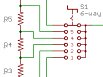
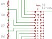
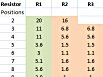
SWITCHES
A 3-position switch is a common requirement:
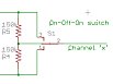
Rx60 and Rx61 have a feature called Selecta which requires a multi-position switch. The wiring diagrams and resistor values in the tables below describe how to set Tx2 up for these. The default throws are 150% but use the values for 100% when that option is enabled. Any analogue channel can be used except those intended for motor control in trains (these are affected by the Inertia feature). The Selecta switch never connects the Tx2 input to 0v or 1.55v. So inputs can also be used for things like Binding which connect the input to 0v to be effective.
|
|
|
|
|
|
TRIM POT
A separate pot can be placed in parallel with a joystick pot to create a more easily adjustable 'mechanical' trim for each channel. Two examples in the link below.