
|
|
DT Tx22 Transmitter Kit
|
 |
 |
 |
DESCRIPTION:
The Kit includes the core components to make a Tx22 transmitter.
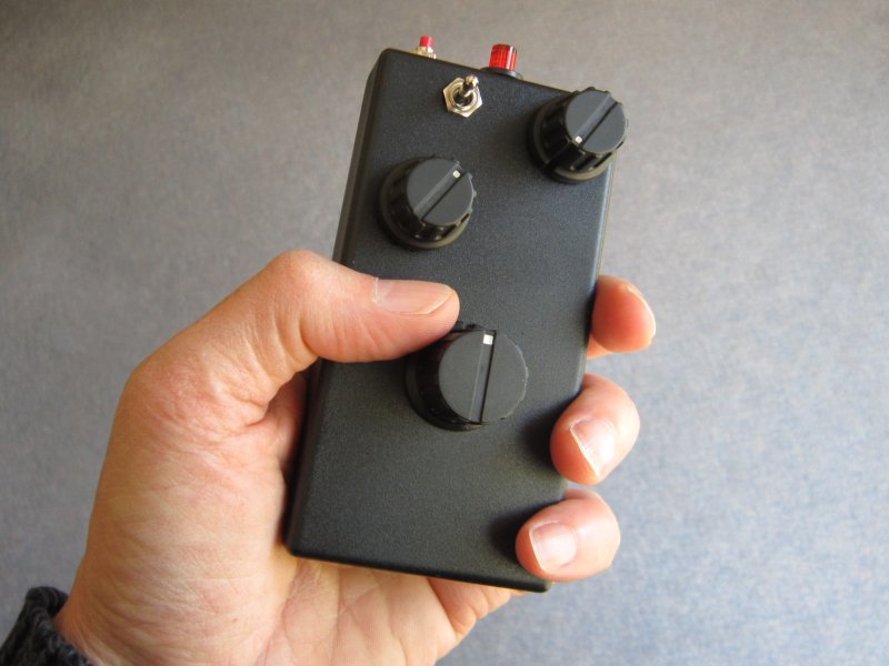
Tx22 is a compact wireless transmitter intended to control model railway train engines.
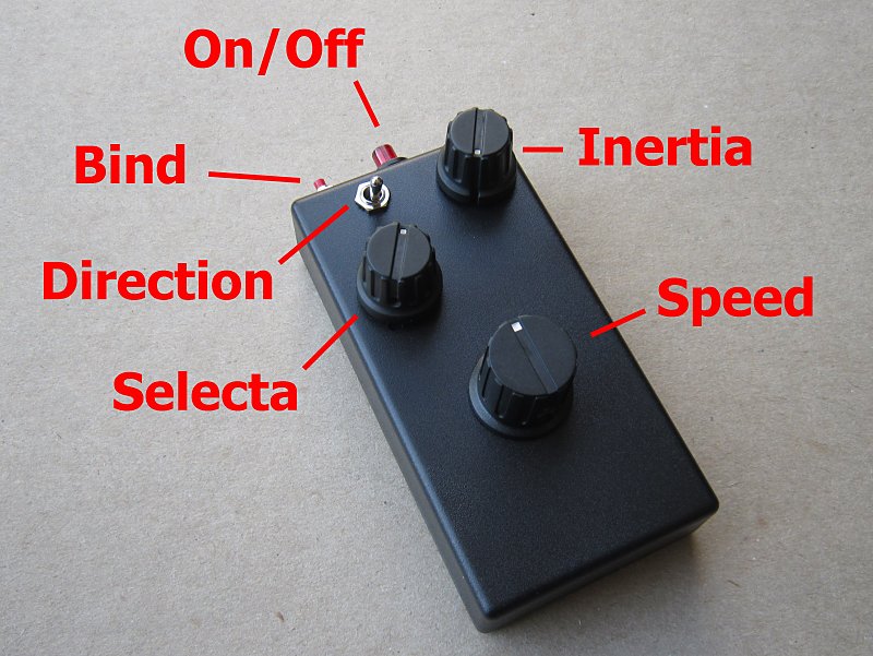
It has controls for Speed, Direction, Inertia, Lights, Coupling and Loco selection (depending on how used).
KIT CONTENTS:
| Tx22 Kit | Item | |
| 1 | Cardboard box | |
| 1 | Medium plastic box | |
| 1 | 3-way Direction toggle switch | |
| 1 | On/Off pushbutton with Led | |
| 1 | Bind pushbutton | |
| 1 | 12-way Selecta rotary switch | |
| 2 | 10k pot 300° rotation with center click (detent) | |
| 1 | Medium Selecta knob (6.3mm) | |
| 1 | Medium Inertia knob (6mm) | |
| 1 | Large Speed knob (6mm) | |
| 1 | 220 resistor (optional) | Red-Red-Brown-Brown |
| 2 | 10k resistor | Brown-Black-Orange-Brown |
| 11 | 2k4 resistor | Red-Yellow-Black-Brown-Brown |
| 1 | 7k5 resistor | Violet-Green-Black-Brown-Brown |
| 1 | 12k resistor | Brown-Red-Black-Red-Brown |
| 1 | 18k resistor | Brown-Grey-Black-Red-Brown |
| 1 | 39k resistor | Orange-White-Black-Red-Brown |
| 1 | 62k resistor | Blue-Red-Black-Red-Brown |
| 2 | 100k resistor | Brown-Black-Black-Orange-Brown |
| 200mm | 2.4mm heatshrink | |
| 1 | PP3 plug | |
| 1 | Tx2 | |
| 1 | Plastic sheet for compartments | |
| 1 | Wiring diagram | |
| 1 | Drill template | |
| 1 | This page (www.DelTang.co.uk/tx22-kit.htm) |
OTHER ITEMS NEEDED:
PP3 9v battery, hookup wire
Solder, Iron, Multimeter, Glue, Drills, Files, Knife, Screwdrivers etc.
WIRING DIAGRAM:
Tx22 circuit
DRILL TEMPLATE:
Tx22 layout
ASSEMBLY:
Wire lengths |
1 |
2 |
3 |
4 |
5 |
6 |
7a |
7b |
8 |
INSTRUCTIONS:
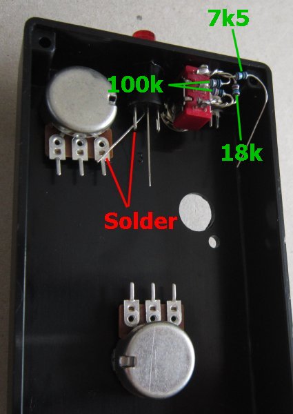
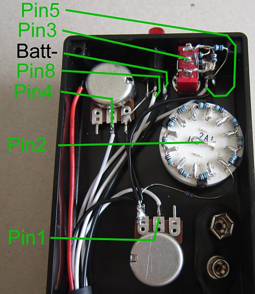
1a. Twist the 100k (x2), 18k and 7k5 resistors together and solder to 3-way switch.
1b. Bend short wire from led and solder to on/off terminal and inertia pot.
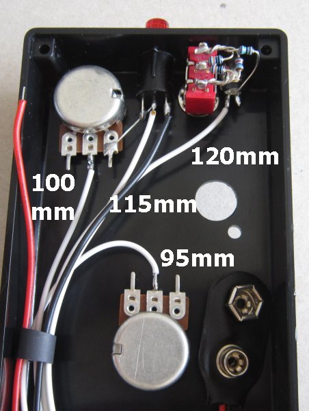
2. Solder 7k5 to bind switch. Solder 4 white wires shown. Solder black PP3 connector wire to on/off switch.
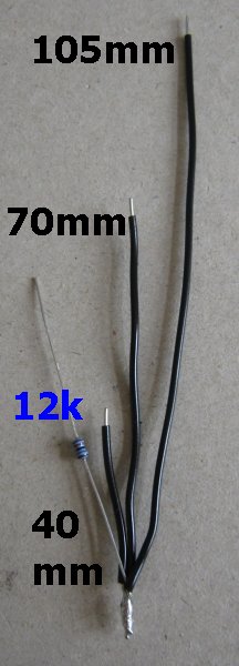
3. Make 'negative wiring harness' with 12k resistor.
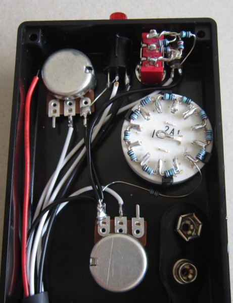
4a. Mark Selecta switch terminal '1'. Bend terminals flat to fit in box. Solder 11x 2k4 resistors starting from position '1'.
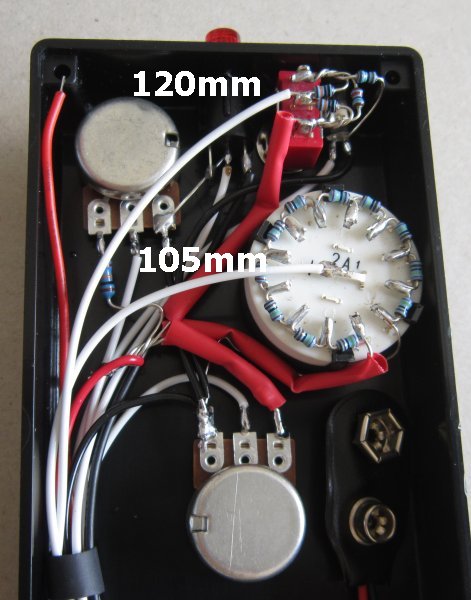
4b. Solder negative wiring harness in place. 12k to '1' and negative wires as shown. The black 105mm wire will be soldered to the Tx2 module later.
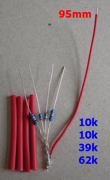
5. Make 3.1v wiring harness with 1 wire and 10k (2), 39k and 62k resistors.
6. Solder 39k to 3-way switch, 62k to position '12' on Selecta switch, and 10k to each pot. Protect from shorts with heatshrink tubing. 95mm red wire will be soldered to 3.1v on Tx2 module later. Add 2 white wires.
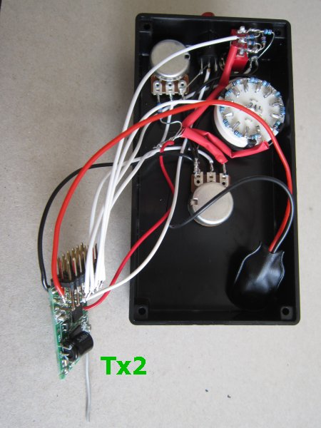
7. Solder wires to Tx2 module.
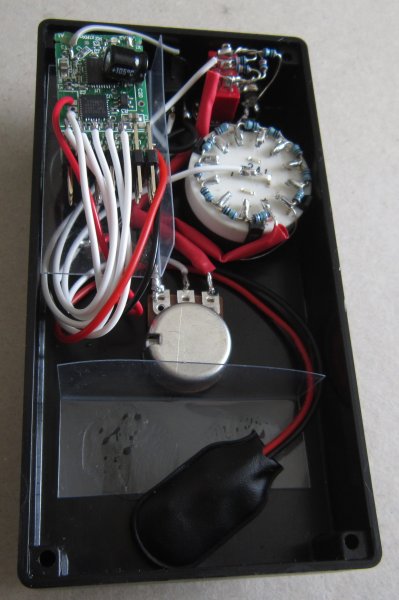
8. Cut/bend/glue plastic sheet for Tx2 module (50mm x 20+10mm) and 9v battery (45mm x 18+18mm).
TIPS:
Glue drill templates to box with Pritt and protect outside of box from scratches while drilling.
The 2 longer wires in the middle of the on/off switch are the Led. The shorter of those goes to negative.
The 220 ohm resistor for the led is optional. It reduces current slightly but is less bright.
The Direction switch leans the opposite way to the terminal it enables