
|
|
Tx3 Instructions (v300)
|
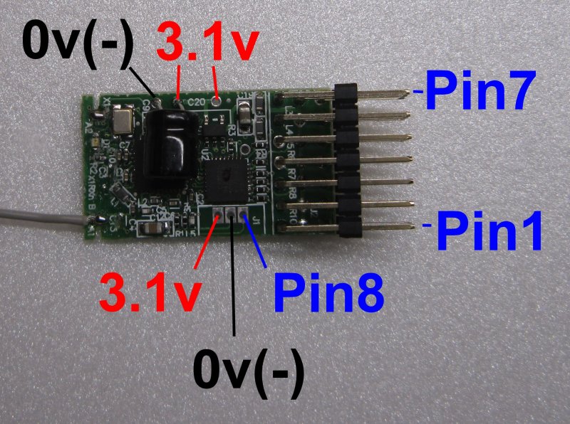 (3.1v is source for Vref) |
 (1-2S lipo or 3-6 AA or 9v PP3) |
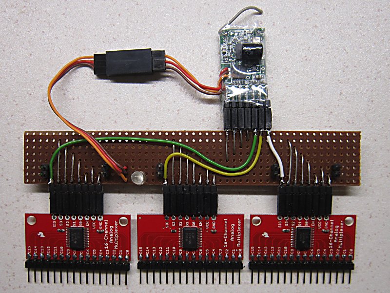 (top) |
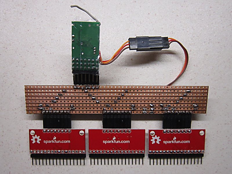 (bottom) |
1. DESCRIPTION:
Transmitter for complex static layouts (eg: model railways).
Only suitable for things that are not changed frequently (eg: lights, points, semaphores, turntables).
Up to 45 unique channels can be controlled with 9 receivers and 3 Mux boards (not supplied).
Can only be used with Rx105 receivers.
All inputs are 'analogue' which means they can be used with potentiometers or switches.
However, the update speed for 45 channels is relatively slow. Switches work well but changes with pots are usually too jerky.
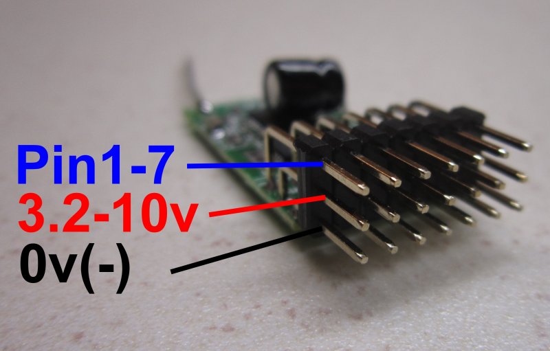
2. TX3 CONNECTIONS
Tx3 has to be used with 1, 2 or 3 Sparkfun Analog/Digital MUX Breakout boards (BOB-09056).
These are available from many suppliers or can be made yourself using a CD74HC4067 chip.
|
Tx3 |
Function |
Comment |
| Pin1: | 'S0' | Common control port for MUX1/2/3 |
| Pin2: | 'S1' | Common control port for MUX1/2/3 |
| Pin3: | 'S2' | Common control port for MUX1/2/3 |
| Pin4: | 'S3' | Common control port for MUX1/2/3 |
| . | . | . |
| Pin5: | MUX1 'SIG' | Analogue input for MUX1 |
| Pin6: | MUX2 'SIG' | Analogue input for MUX2 |
| Pin7: | MUX3 'SIG' | Analogue input for MUX3 |
| . | . | . |
| Pin8 (side): | LED2 | External led |
| 3.1v: | 'VCC' |
Regulated power supply for MUX boards Reference voltage for switches |
3. MUX CONNECTIONS
One, two or three MUX boards can be used.
Five inputs are transmitted to each of up to nine Rx105 receivers.
|
. |
MUX1 |
MUX2 |
MUX3 |
Comment |
| SIG: |
Pin5 |
Pin6 |
Pin7 |
Analogue input from MUX1/2/3 to Tx3 |
| . | . | . | . | . |
| S0: |
Pin1 |
Pin1 |
Pin1 |
Common control ports |
| S1: |
Pin2 |
Pin2 |
Pin2 |
Common control ports |
| S2: |
Pin3 |
Pin3 |
Pin3 |
Common control ports |
| S3: |
Pin4 |
Pin4 |
Pin4 |
Common control ports |
| . | . | . | . | . |
| VCC: |
3.1v |
3.1v |
3.1v |
3.1v Positive |
| GND: |
Ground |
Ground |
Ground |
Negative |
| EN: |
Ground |
Ground |
Ground |
Enable |
| . | . | . | . | . |
| C0: | Rx1 Ch1 | Rx4 Ch1 | Rx7 Ch1 | Analogue input from switch |
| C1: | Rx1 Ch3 | Rx4 Ch3 | Rx7 Ch3 | as above |
| C2: | Rx1 Ch4 | Rx4 Ch4 | Rx7 Ch4 | as above |
| C3: | Rx1 Ch5 | Rx4 Ch5 | Rx7 Ch5 | as above |
| C4: | Rx1 Ch6 | Rx4 Ch6 | Rx7 Ch6 | as above |
| . | . | . | . | . |
| C5: | Rx2 Ch1 | Rx5 Ch1 | Rx8 Ch1 | Analogue input from switch |
| C6: | Rx2 Ch3 | Rx5 Ch3 | Rx8 Ch3 | as above |
| C7: | Rx2 Ch4 | Rx5 Ch4 | Rx8 Ch4 | as above |
| C8: | Rx2 Ch5 | Rx5 Ch5 | Rx8 Ch5 | as above |
| C9: | Rx2 Ch6 | Rx5 Ch6 | Rx8 Ch6 | as above |
| . | . | . | . | . |
| C10: | Rx3 Ch1 | Rx6 Ch1 | Rx9 Ch1 | Analogue input from switch |
| C11: | Rx3 Ch3 | Rx6 Ch3 | Rx9 Ch3 | as above |
| C12: | Rx3 Ch4 | Rx6 Ch4 | Rx9 Ch4 | as above |
| C13: | Rx3 Ch5 | Rx6 Ch5 | Rx9 Ch5 | as above |
| C14: | Rx3 Ch6 | Rx6 Ch6 | Rx9 Ch6 | as above |
| . | . | . | . | . |
| C15: | Bind | - | - | Digital input with weak pullup |
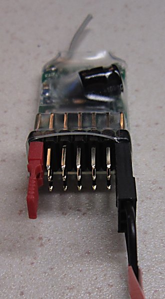
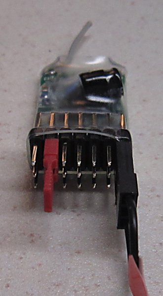
4. NUMBER OF MUXES:
Tx3 is configured for one Mux. Up to three are possible if you change the setting:
 |
 |
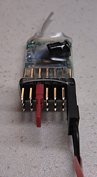 |
1. Connect the Pin7 signal pin to negative with the large plug. 2. Connect Pin1, Pin2 or Pin3 signal to positive with small plug. 3. Switch the transmitter ON. The led will flash 1-3 times. 4. Remove plugs and switch transmitter OFF. |
5. ANALOGUE INPUTS (C0-C14):
The voltage on these inputs should not exceed 3.6v.
Only 0-1.55v can be measured as an analogue/proportional value. 1.55-3.6v gives full throw.
Tx3 has a 3.1v reference voltage which can be divided with resistors to give 0-1.55v.
A 10k pot can be used with a 10k resistor to control voltage in a proportional manner between 0-1.55v.
However, the update speed for 45 channels is too slow to give smooth changes.
Switches work well:
* 3-position switches need resistors to create values between 0-1.55v from the 3.1v reference.
* 2-position switched inputs can simply be toggled between 0 and 3.1v to achieve minimum and maximum values.
6. CIRCUIT DIAGRAM:
TX3
7. LED:
In normal use, the led on Tx3 will be on continuously but flicker slightly.
Pin8 can drive an external led. Tx3 has an on-board 180ohm resistor so an external resistor is not normally needed.
8. BINDING:
Connect a 'normally open' pushbutton between C15 of MUX1 and Ground.
Press and hold the Bind button when switching Tx3 on to start binding.
The led with flash for a few seconds.
9. GETTING STARTED:
1. Tx3 is supplied for use with one mux. Change to 2 or 3 if needed.
2. Connect switches to the Mux inputs. Inputs with nothing connected will often mirror another input and appear eratic.
3. MUX1 controls Selecta Numbers 1/2/3. MUX2 controls 4/5/6. MUX3 controls 7/8/9.
4. Set Rx105 to the correct Selecta Number (1-9).
5. Bind each Rx105 with Tx3.
6. The Rx105 led should come on solid after binding.
7. Use a servo to check that the Rx105 outputs work as intended.
8. Swop +/- terminals on Tx3 switches to reverse servo direction.
9. Set up Rx105 throws for each servo so they do not jam at full travel.