
|
|
Rx105 Instructions (v110)
|
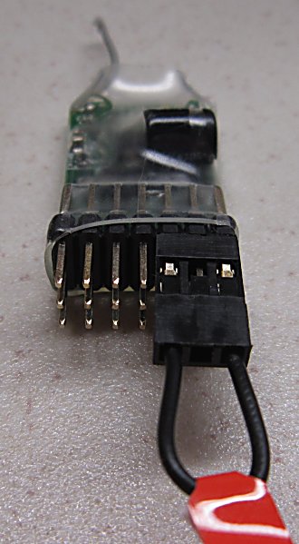
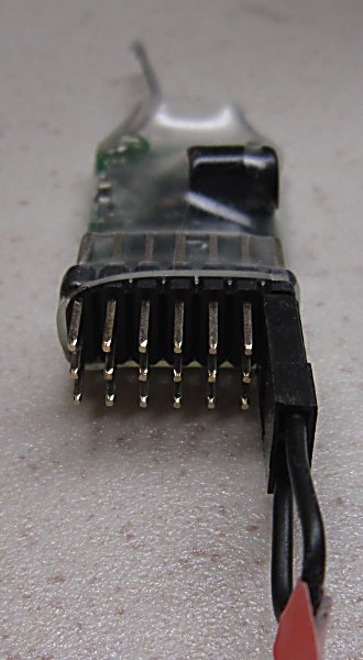
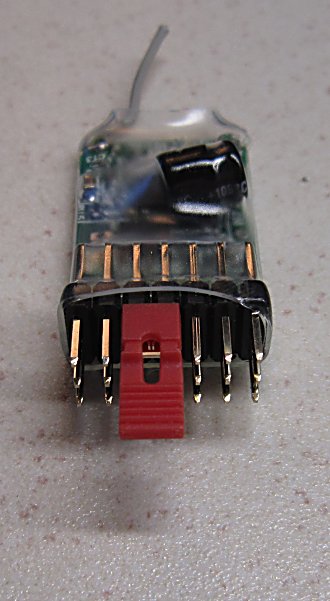
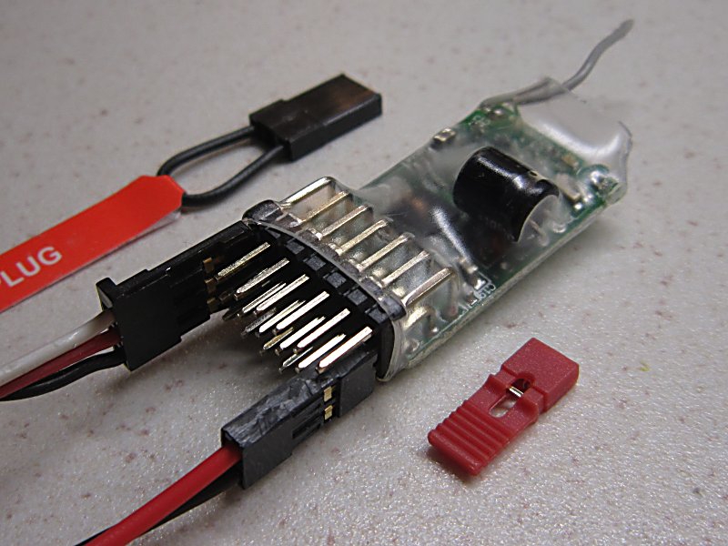 servo |
 connections |
1. DESCRIPTION:
Receiver for model railway layouts.
Mainly intended for Lights and Servo control (eg: points, semaphores, turntables, simple animation).
Nine receivers can be used with one Tx3 to control up to 45 channels.
2. VARIANTS 1,2,3,4
Switches on transmitters control 'channels'. They are numbered 1-7.
Each output on the receiver is controlled by one channel.
A choice of three types of output are available.
|
Channel |
Rx105-1 |
Rx105-2 |
Rx105-3 |
Rx105-4 |
Comment |
|
| Purpose: | . |
Servo functions (eg: Points) |
Servo functions (eg: Semaphores) |
On/Off functions (eg: lights) |
Mixed functions (servos and lights) |
. |
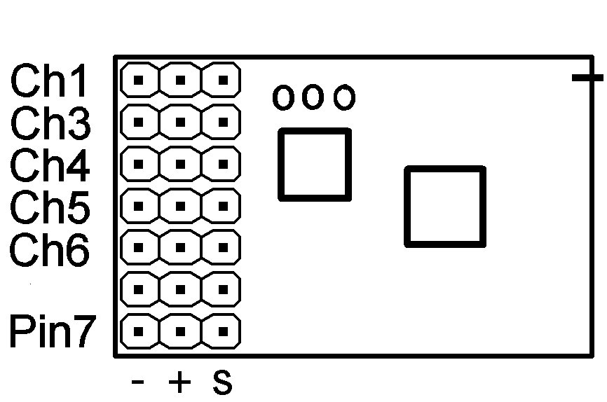
| Pin1: | Ch1 | Normal servo | 'Signal' servo | Light | Normal servo | Adjustable throws |
| Pin2: | Ch3 | Normal servo | 'Signal' servo | Light | Normal servo | Adjustable throws |
| Pin3: | Ch4 | Normal servo | 'Signal' servo | Light | Normal servo | Adjustable throws |
| Pin4: | Ch5 | Normal servo | 'Signal' servo | Light | 'Signal' servo | Adjustable throws |
| Pin5: | Ch6 | Normal servo | 'Signal' servo | Light | 'Signal' servo | Adjustable throws |
| . | . | . | . | . | . | . |
| Pin6: | Ch6 | Light | Light | Light (low) | Light | . |
| Pin7: | Ch5 | Light | Light | Light (low) | Light | . |
| Pin8 (side): | Ch4 | Light | Light | Light (low) | Light | . |
Outputs in all variants can be changed to be any mix of the above features (see PROGRAMMING below).
Variants 5-8 also exist for transmitters like Tx27 that can control 7 channels (see VARIANTS 5,6,7,8 below).
Ch2 is normally used for Selecta (see SELECTA NUMBER below).
3. RECEIVER LED:
The led will flash 1-12 times while the transmitter is off. This is the 'Selecta Number' (see below).
These flashes stop as soon as a signal is detected. The led is then on solid with perfect reception and off with signal loss.
4. OPERATION WITHOUT TRANSMITTER:
Outputs go to a saved position on startup. The transmitter can be left off.
New positions are saved automatically once a minute when signals are being received. Small changes may not be saved.
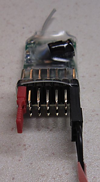
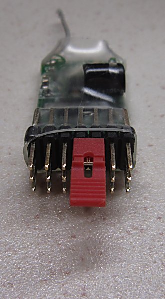
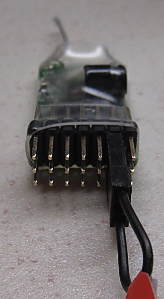
5. BINDING:
Each receiver needs to be bound to the transmitter once:
 |
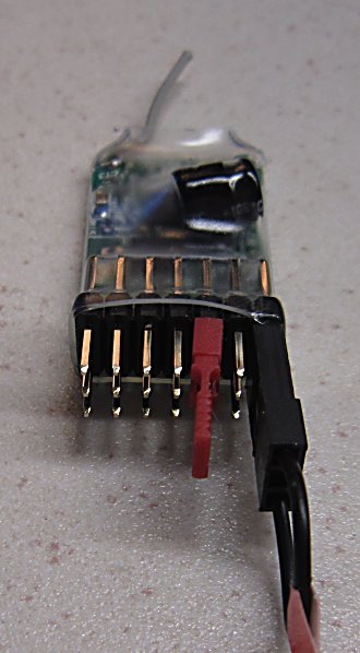
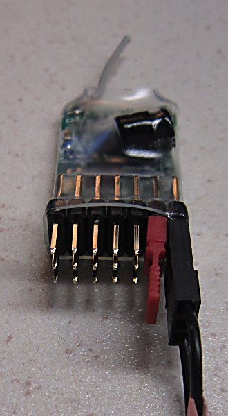
1. Put the large bind plug on Signal pins 5 & 7. Switch Rx on. Led will flash rapidly. Remove bind plug. 2. Hold Tx bind switch and switch Tx on. Led should flash slower for several seconds. 3. Bind is complete when Led stays On. |
If Led does not come on within 10sec or continues flashing every 2sec (=scanning) the bind has failed. Switch Tx and Rx off, move them closer or further apart and retry. Binding is most reliable when no other RC 2.4 Tx’s are on.
6. SELECTA NUMBER:
Selecta is a technique for selecting individual receivers based on the position of a controlling channel (Ch2).
This allows one transmitter to send different channel positions to many receivers.
* Tx27 is intended to be used with 1 or 2 receivers, both with the same Selecta Number.
This is the default for Rx105 and requires no setup.
* Tx22 can control 12 receivers, selected manually, only one active at any time.
This requires the Selecta Number to be set to a number matching a Selecta switch position (eg: '3' for 3 o'clock position).
* Tx3 can control 9 receivers, all continuously by automatically hopping between them.
This requires each receiver to be given a different Selecta Number (1-9).
 |
 |
 |
 |
 |
 |
 |
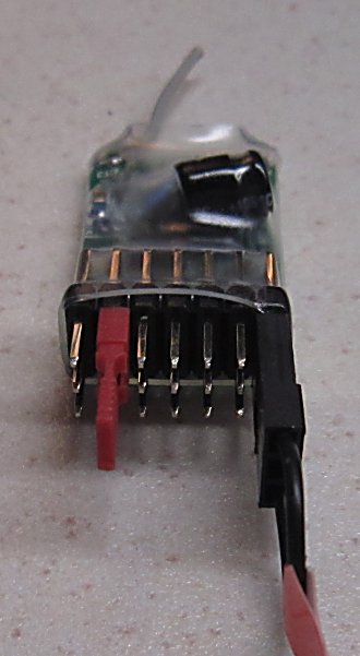
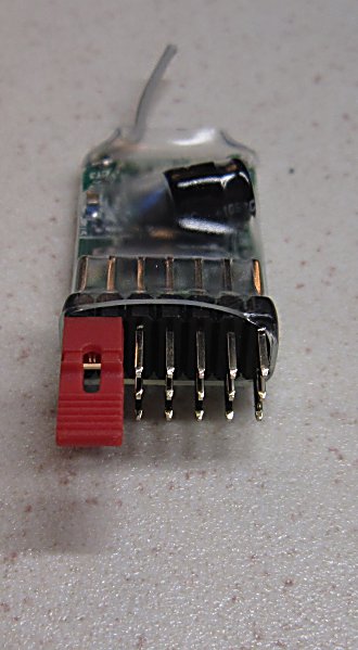
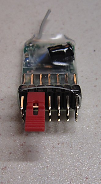
1. Connect the Pin7 signal pin to negative with the large plug. 2. Connect one (or more) of Pins 1-6 signal to positive with small plug. 3. Switch the receiver ON. The led will flash 0-12 times. 4. Remove plugs and switch receiver OFF and ON to use normally. |
To set numbers 7-12 use two or more small plugs to 'sum' (eg: Pin2 + Pin5 = 7).
These numbers should match Selecta switch positions but is not guaranteed.
Tx27 needs Selecta disabled which is the number is set to '0'. This is how Rx105 is provided.
7. ON / OFF LIGHTS:
This option makes the output toggle ON or OFF. It is suitable for driving an led direct.
The default settings are for the output to be ON when the controlling channel is HIGH (except where indicated in variants 3 and 7).
These pins are 3.1v when ON. They have on-board 180ohm resistors so limit current to around 12mA with an led.
Connect the led between the Signal pin and Negative (-).
The feature can recognise three channel positions (High, Mid and Low).
This allows one channel to control up to 3 lights on separate outputs.
The activating channel and position can be configured through Programming.
8. NORMAL SERVO (eg: Points):
Points and other mechanical devices can be operated with a hobby servo.
These may require precise adjustment of servo arm movement (throws) to avoid jamming at the ends of travel.
Each output is fully proportional so can be controlled with a pot or a switch.
9. SIGNAL SERVO (Semaphores):
Signals can be operated with a normal hobby servo.
Rx105 makes the servo 'bounce' before coming to rest.
This option can be controlled with a pot or switch but is not 'proportional'.
The servo is made to go to one of three positions (High, Mid and Low) at a controlled speed.
The Mid position is fixed. The High and Low positions can be changed by adjusting servo throws.
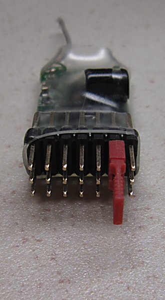
10. CHANGING SERVO THROWS:
Phase 1 - Select the output to change:
 |
 |
 |
 |
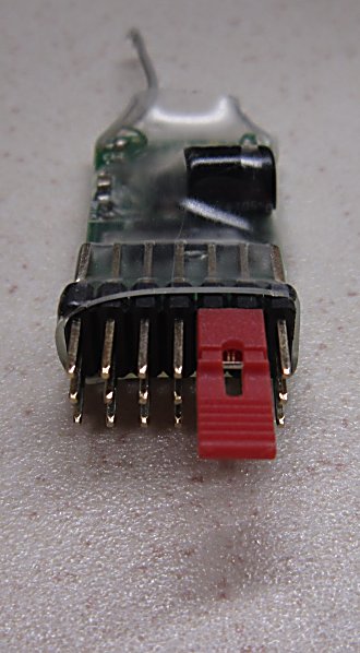 |
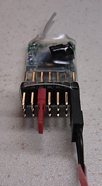
Select one Pin to change per startup. |
1. To change Pin 1 (Ch1) put the small bind plug on Signal pins 1 & 2.
2. To change Pin 2 (Ch3) put the small bind plug on Signal pins 2 & 3.
3. To change Pin 3 (Ch4) put the small bind plug on Signal pins 3 & 4.
4. To change Pin 4 (Ch5) put the small bind plug on Signal pins 4 & 5.
5. To change Pin 5 (Ch6) put the small bind plug on Signal pins 5 & 6.
6. Switch Rx on. Led will toggle every 1/2 second. Remove bind plug.
7. Switch Tx on. Led will flash until it locks on to the Tx signal and then stay off. A servo on the chosen Pin can then be controlled with the Tx.
Phase 2 - Make changes to the selected output:
Changes are made by connecting the Signal pin to Positive(+) or Negtive(-).
Only the output being changed works while making changes to it.
Low and High side throws can be changed by up to 31 steps each way.
The led will flash and throws will change one step per second while a plug is installed.
The led stays on for 3s when throws are returned to their 'mid' position.
The led stays on solid when you reach the end of the adjustment range.
|
|
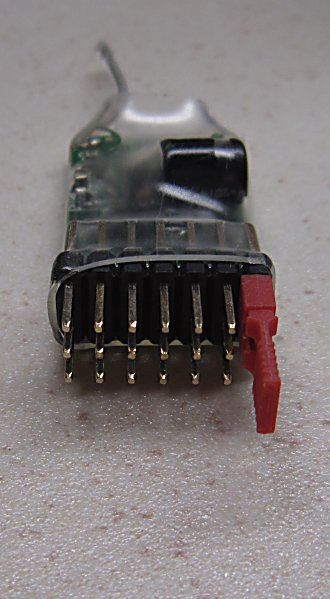 |
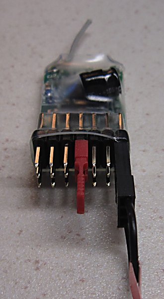
High side Throws 8. To increase high side throws, use the large bind plug to connect the Pin7 signal pin to negative. 9. To decrease high side throws, use the small bind plug to connect the Pin7 signal pin to positive. |
 |
 |
Low side Throws 10. To increase low side throws, use the large bind plug to connect the Pin6 signal pin to negative. 11. To decrease low side throws, use the small bind plug to connect the Pin6 signal pin to positive. |
12. Changes are saved whenever you remove a plug.
13. Remove all plugs and switch the Rx off and on to use all outputs normally.
11. PROGRAMMING:
All Rx105 outputs can be changed with Prog3 or Prog4 to any of the available functions.
All outputs can be controlled with any channel number.
The options available can be found here.
To minimise stock holdings, shops can change variants with PROG2.
12. POWER:
Rx105 can be powered with 3.2-10v but 5v is the norm.
Servos are usually powered through the receiver +/- pins which are all common.
Most servos are intended for 5v operation (but check their specification).
13. PREVIOUS VERSIONS:
14. VARIANTS 5,6,7,8:
Variants 1-4 have five outputs with adjustable throws (Ch1,3,4,5,6). Tx27 can control seven channels (Ch1-7).
Variants 5-8 are set up to control the extra two channels (Ch2,7). Channel numbers are the only difference between variants 1-4 and 5-8.
|
Channel |
Rx105-5 |
Rx105-6 |
Rx105-7 |
Rx105-8 |
Comment |
|
| Purpose: | . |
Servo functions (eg: Points) |
Servo functions (eg: Semaphores) |
On/Off functions (eg: lights) |
Mixed functions (servos and lights) |
. |
| Pin1: | Ch2 | Normal servo | 'Signal' servo | Light | Normal servo | Adjustable throws |
| Pin2: | Ch7 | Normal servo | 'Signal' servo | Light | Normal servo | Adjustable throws |
| Pin3: | Ch6 | Normal servo | 'Signal' servo | Light | Normal servo | Adjustable throws |
| Pin4: | Ch4 | Normal servo | 'Signal' servo | Light | 'Signal' servo | Adjustable throws |
| Pin5: | Ch3 | Normal servo | 'Signal' servo | Light | 'Signal' servo | Adjustable throws |
| . | . | . | . | . | . | . |
| Pin6: | Ch1 | Light | Light | Light (low) | Light | . |
| Pin7: | Ch2 | Light | Light | Light (low) | Light | . |
| Pin8 (side): | Ch3 | Light | Light | Light (low) | Light | . |