
|
|
Rx45-22 Instructions (v511)
|
|
|
|
1. DEFAULT SETUP
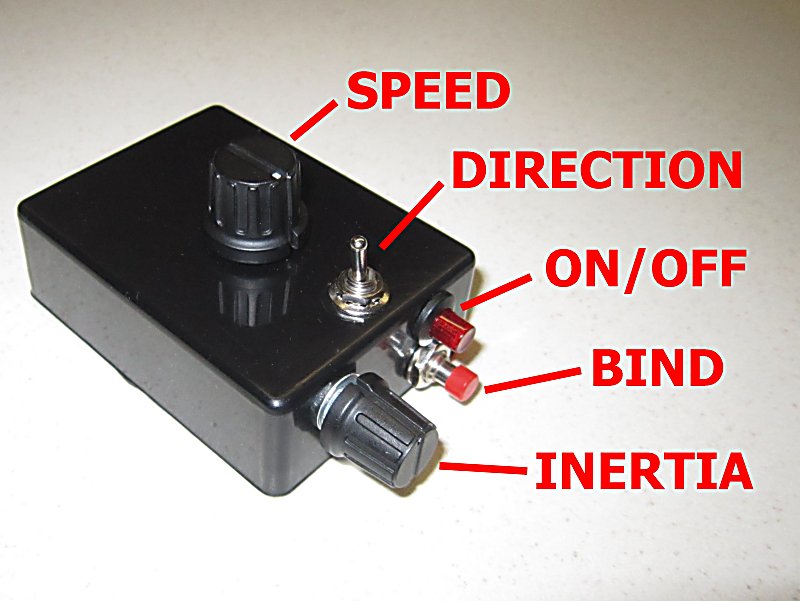
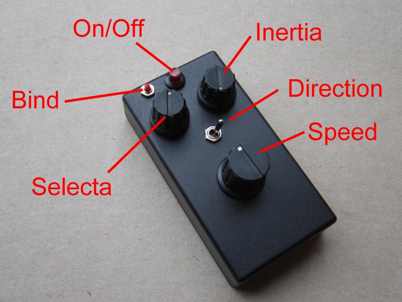
- Train with center off motor control intended for Tx21/Tx22.
- The 'direction' switch can control 4 lights or on/off functions and a servo.
- The 'bind' button can operate 2 lights and a servo.
- For the Rx to work the Selecta switch has to be in the position learned during binding.
- All settings can be customised / re-configured.
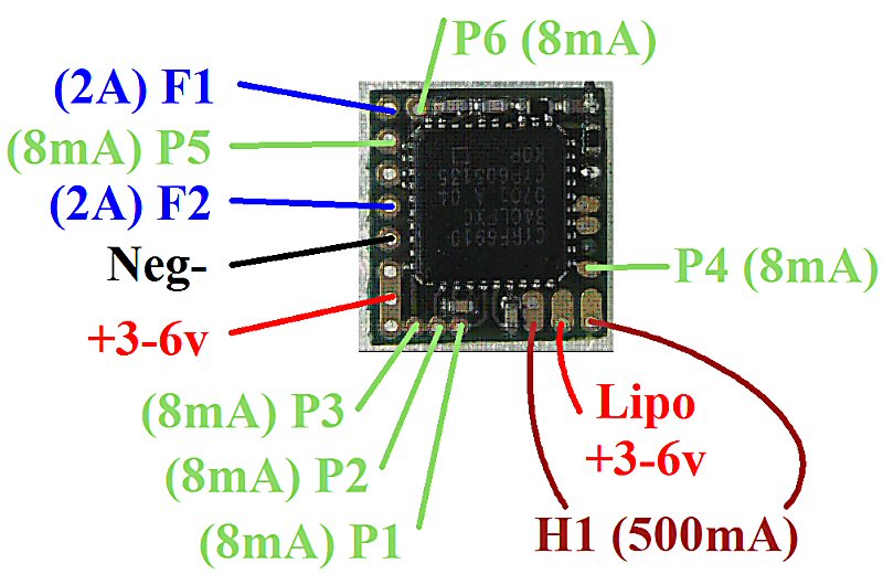
| Output | Type | Channel | Other |
| H1: | Motor 'center off' control | Ch1 'speed' knob |
130Hz PWM frequency 0.5A max stall current |
| F1: | On/Off light or buzzer | Ch3 'direction' switch |
Tx21: Right=On Tx22: Up=On Led needs current limiting resistor |
| F2: | On/Off light or buzzer | Ch3 'direction' switch |
Tx21: Left=On Tx22: Down=On Led needs current limiting resistor |
| P1: | On/Off light (front) | Ch3 'direction' switch |
Tx21: Right=On Tx22: Up=On P1 is also set up as 'LED2' Led needs current limiting resistor |
| P2: | On/Off light (rear) | Ch3 'direction' switch |
Tx21: Left=On Tx22: Down=On Led needs current limiting resistor |
| P3: |
Servo |
Ch3 'direction' switch | |
| P4: | Servo |
Ch5 'bind' button |
|
| P5: | On/Off light |
Ch5 'bind' button |
Long press to toggle on/off (>2s) Led needs current limiting resistor |
| P6: | On/Off light |
Ch5 'bind' button |
Short press to toggle on/off (<1s) Led needs current limiting resistor |
|
Selecta |
Enabled |
Ch2 |
Up to 12 locos can be associated with Selecta switch on Tx22 Outputs 'hold' their settings when deselected |
| Arming/Activation: | Mid-stick to enable | Ch1 | |
| LVC |
Mid-stick to acknowledge |
Ch1 | 'LED2' 2-flash if triggered |
| LED2 | External LED | P1 | Shows useful receiver activity |
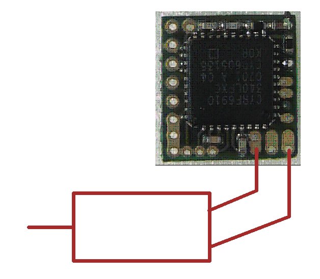
2. EXAMPLE CONNECTIONS:
|
|
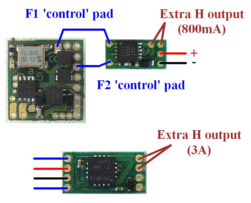
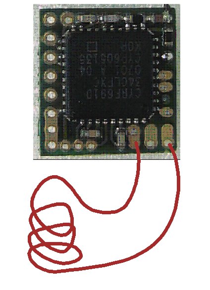
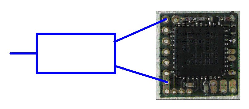
for extra H output |
|
|
|
|
LEDs with 1S Lipo:
Led's driven from P outputs only require a current limiting resistor (8mA max).
Led's driven from F outputs only require a current limiting resistor (2A max).
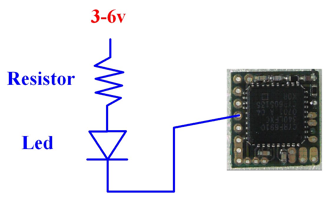
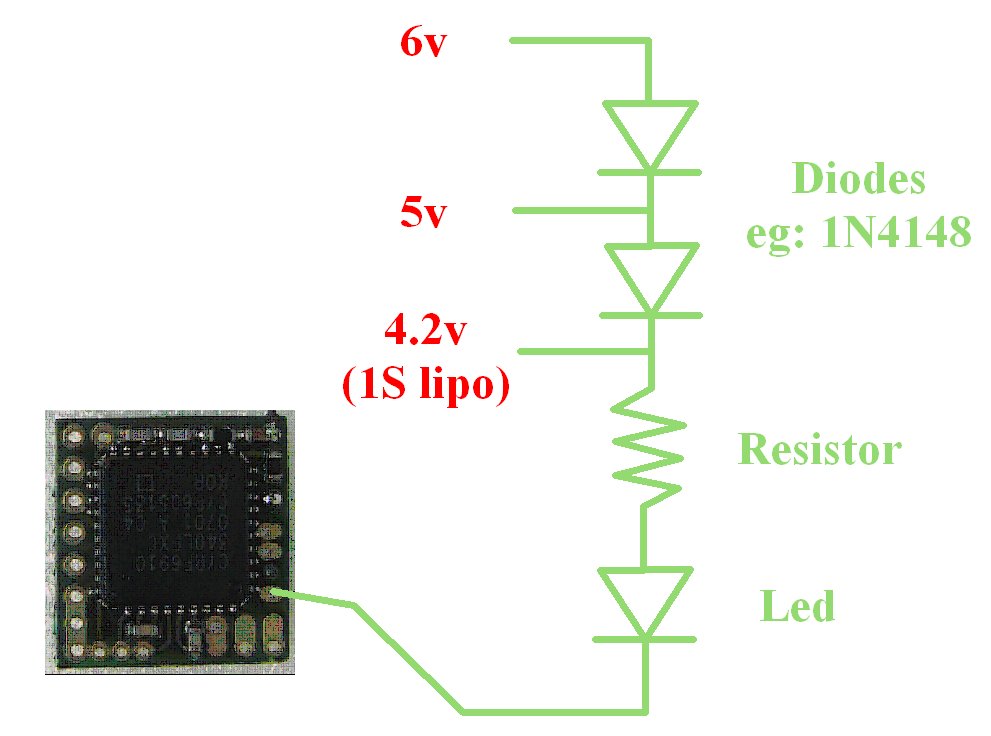
LEDs with 5-6v:
'P' outputs are 3v when 'off' and 0v when 'on'. So when used with higher voltages, the leds driven from P outputs also need diodes to reduce the voltage. This is because 5 or 6v is high enough above the 3v output to make Leds conduct even when P outputs are 'off'. An example is shown in the Led (P4) diagram.
Led's driven from F outputs only require a current limiting resistor when operated off any voltage up to 6v.
GRAIN of WHEAT:
Grain of Wheat bulbs usually draw >8mA so are not suitable for use with P outputs (unless buffered with a transistor).
Grain of Wheat bulbs can be driven from F outputs. F outputs allow the intensity to be varied with stick movement or 'Travel Adjust'.
3. CHANGING OUTPUTS:
All outputs can be customised / re-configured:
PROGRAMMING
4. GENERAL:
The Rx is not insulated.
The PCB is thin so do not bend it.
5. LED:
Led On = perfect reception (real-time indicator).
1 flash = Scanning (~2sec between flashes; wrong model if never stops).
2 flash = Brownout (receiver voltage went too low; check battery/servo load).
6. FAILSAFE:
Outputs are not driven (do nothing) on startup and while scanning.
Outputs 'hold' on short signal losses (<1sec) and then do nothing (>1s).
7. BINDING:
1. Switch Rx on and wait ~20s until led flickers fast.
2. Switch Tx on in bind mode and Rx led should flash slowly and then go solid.
3. Change distance between Tx/Rx if binding does not work.