
|
|
Rx65-6-3A2 Instructions (v611)
|
|
|

|

|
1. DEFAULT SETUP
|
Item |
Setting | Details |
|
Purpose: |
Rx65-6 |
'Boat' setup for use with joystick transmitter |
|
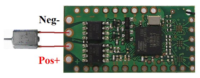
Red wire positive (+) Black wire negative (-) |
Battery |
3-18v (if no BEC) Observe polarities |
|
H1 output |
Motor 1 Ch3 Forward/reverse |
Integrated forward/reverse ESC for brushed motors H1/H2 used as a pair; Center off 50% mix |
|
H2 output |
Motor 2 Ch2 Steering |
Integrated forward/reverse ESC for brushed motors H1/H2 used as a pair; Center off 50% mix |
|
F1 output 'A' (P13) |
On/Off Ch5 Pump |
Start disconnected, 0v (on) when channel is Low Momentary action |
|
F2 output 'B' (P14) |
On/Off Ch4 Radar |
Start disconnected, toggle when channel is Low Latching action |
|
F3 output 'C' (P15) |
On/Off Ch4 Search light |
Start disconnected, toggle when channel is High Latching action, LED2 enabled |
|
F4 output 'D' (P5) |
On/Off Ch1 |
Start disconnected, toggle when channel is High Latching action ('D' is controlled by P5) |
| P1 | Servo | Ch2 |
| P2 | Servo | Ch3 |
| P3 | Servo | Ch4 |
| P4 | On/off | Ch1 toggle when channel is low, latching |
| P5 | On/off | Ch1 toggle when channel is high, latching (P5 controls 'D') |
| P6 | Flasher (0.5s) | Ch4 right >2s toggle on/off |
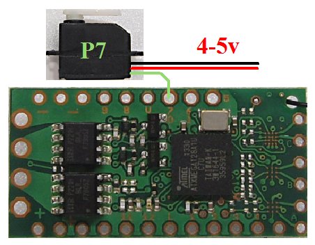
| P7 | On/off | Ch6 on when channel is low, momentary |
|
L input |
Auto-detect |
Monitors single cell lipo when used with a voltage booster |
|
Arming |
Enabled |
Ch3 to center position (off) |
|
Low Voltage Cutoff (LVC) |
Enabled |
Led 5-flash if triggered |
| Failsafe | Enabled |
Motor cuts on signal loss |
| Inactivity Sleep | Disabled |
2. EXAMPLE CONNECTIONS:
|
|
|
|
|
|
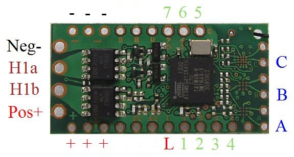
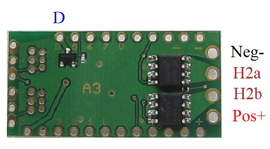
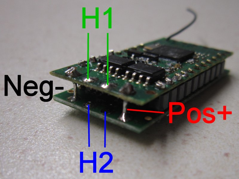
'H' outputs are intended for brushed motors. H1 and H2 have different settings and are intended to be used independantly. H1 is on the main receiver board which has the green led. H2 is on the simpler daughter board marked 'A3'. H1 and H2 both have 3A ratings. This is a maximum 'worst case' value usually measured by connecting a fully charged battery direct to a stalled motor.
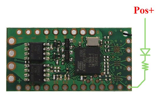
'P' outputs are either 3.5v or 0v (ground). Leds need resistors to limit current to no more than 20mA. High brightness leds allow a lower current which is preferred (eg: 2-5mA). Google will reveal how to select resistor values but 220-470ohms will be safe starting values.
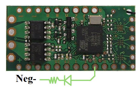
'F' outputs are buffered with a fet. They are 0v (ground) when on and floating (disconnected) when off. Up to 2A is possible but lower currents are much better. Current-limiting resistors are required for leds. The load is normally connected to positive and the F output provides a path to ground to switch it on. F outputs are marked with letters on the receiver (A, B, C and D). The are programmed as P outputs (P13, P14, P15 and P5). eg: F1 = A = P13.
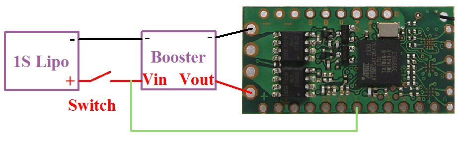
The 'L' pad monitors a single cell lipo when used with a voltage booster. This allows the motor to be powered with a boosted voltage and benefit from the convenience of a single lipo. The receiver will cut power to the motor when the voltage falls to 3v (LVC). The L pad is not intended for use when powering a receiver direct from a single lipo.
3. BINDING
Bind once:
1. Switch Rx on and wait ~20s until led flickers fast.
2. Switch Tx on in bind mode.
3. Rx led should flash slowly; wait for it to go solid.
Change distance between Tx/Rx if binding does not work.
4. LED:
Led On = perfect reception (real-time indicator).
1 flash = Scanning (~2sec between flashes; no signal or not bound if never stops).
5 flash = LVC/Brownout (voltage went too low; check battery/motor load).
5. PAPERCLIP CHANGES:
The following changes can be made by simply shorting two pads together (eg: with a paperclip):
1. Perform a 'Hard reset' (factory reset).
2. Change motor control between 'low off' and 'center off'.
3. Enable/disable LVC (eg: when using Nicads, NiHMs, LiFe cells).
4. Enable/disable Selecta.
5. Enable/disable Cruise Control/Failsafe.
'Paperclip' changes
6. PROGRAMMING:
This receiver has many other options that are described on the features page.
These are changed using a technique called 'programming': v611.