
|
|
Tx72 Transmitter Kit
|
 |
 |
 |
DESCRIPTION:
The Kit includes the core components to make a Tx72 transmitter.
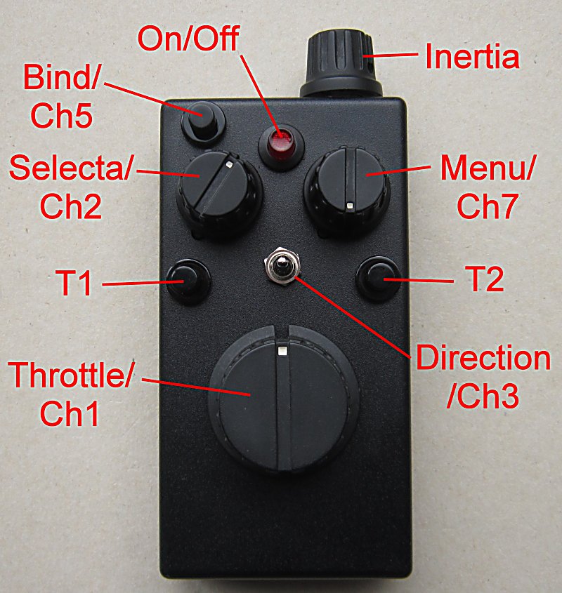
Tx72 is a compact wireless transmitter intended to control model railway train engines.
It has controls for Speed, Direction, Inertia, Lights, Loco selection and Menu control.
KIT CONTENTS:
| Qty | Item | |
| 1 | Medium plastic box | |
| 1 | 3-way latching toggle switch | |
| 1 | On/Off pushbutton with Led | |
| 3 | Pushbutton (Black, Orange, Turquoise) | |
| 2 | 12-way rotary switch | |
| 1 | 10k pot 300° rotation with center click (detent) | |
| 1 | 10k pot 300° rotation | |
| 2 | Medium Selecta/Menu knob (6.3mm) | |
| 1 | Medium Inertia knob (6mm) | |
| 1 | Large Speed knob (6mm) | |
| 22 | 2k4 resistor | Red-Yellow-Black-Brown-Brown |
| 1 | 7k5 resistor | Violet-Green-Black-Brown-Brown |
| 2 | 10k resistor | Brown-Black-Black-Red-Brown |
| 2 | 12k resistor | Brown-Red-Black-Red-Brown |
| 1 | 15k resistor | Brown-Red-Black-Green-Brown |
| 1 | 18k resistor | Brown-Grey-Black-Red-Brown |
| 1 | 39k resistor | Orange-White-Black-Red-Brown |
| 1 | 47k resistor | Brown-Red-Black-Violet-Yellow |
| 1 | 62k resistor | Blue-Red-Black-Red-Brown |
| 2 | 100k resistor | Brown-Black-Black-Orange-Brown |
| 360mm | 2.4mm heatshrink for wires | |
| 50mm | 30mm heatshrink for Tx2 | |
| 1 | Plastic sheet for battery compartment | |
| 1 | PP3 plug | |
| 1 | Tx2-Cap | |
| 1 | Circuit diagram | |
| 1 | Drill template | |
| 1 | Wiring guide | |
| 1 | This page (www.DelTang.co.uk/tx72a-kit.htm) |
OTHER ITEMS NEEDED:
PP3 9v battery, hookup wire, contact adhesive
Solder, Soldering iron, Drills, Files, Knife, Screwdrivers etc.
CIRCUIT DIAGRAM:
Tx72 circuit
DRILL TEMPLATE:
Tx72 drill
WIRING GUIDE:
Tx72 wiring
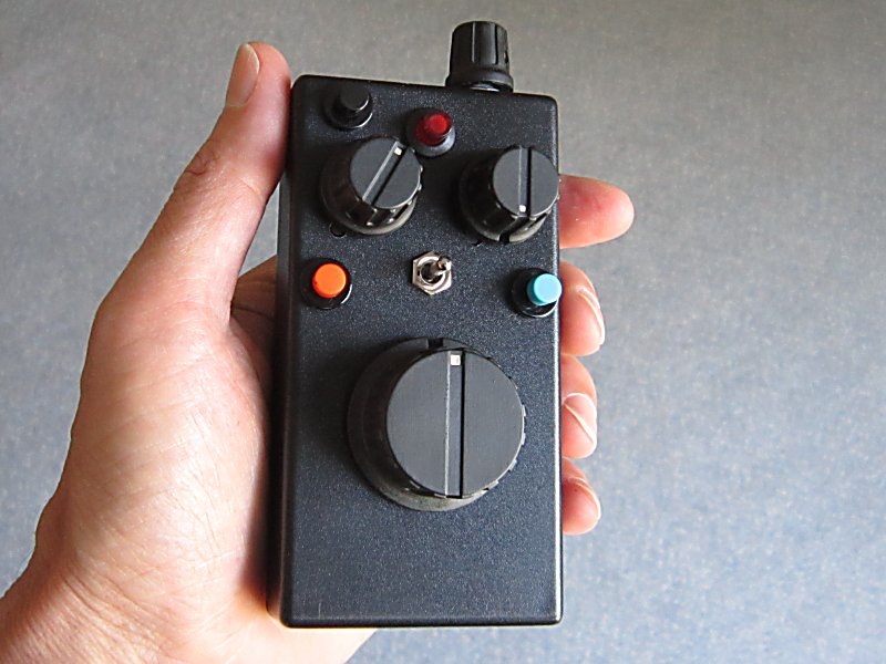
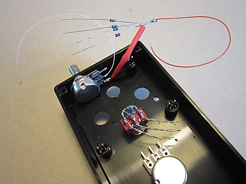
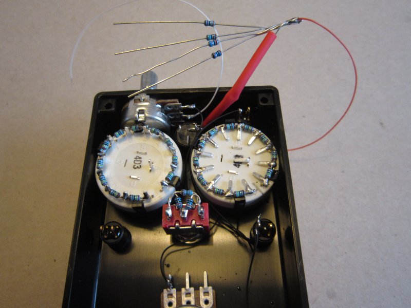
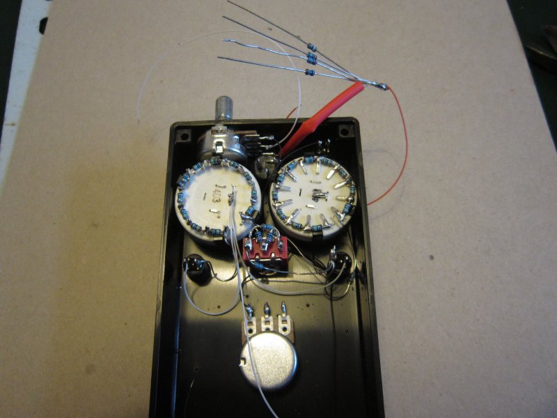
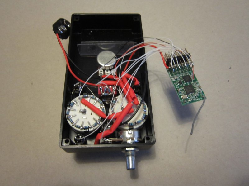
ASSEMBLY EXAMPLE (click to enlarge):
|
|
|
|
|
|
NOTES:
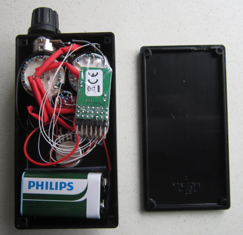
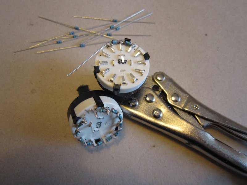
NB: One 12-way switch MUST have its pins folded down flat for there to be enough space for Tx2 above it.
1. The circuit diagram shows the required connections. The photos and wiring guide are examples of how it can be done.
2. It is easiest to press the black plastic pushbutton into a 7mm hole using a medium knob and nut as spacer.
3. The 'Tx2' radio module is powered with 9v. Tx2 has an on-board regulator which provides a 3.1v reference voltage to the other components.
4. The 2 longer wires in the middle of the on/off switch are 'Led2'. The shorter of those is marked '-' and goes to negative.
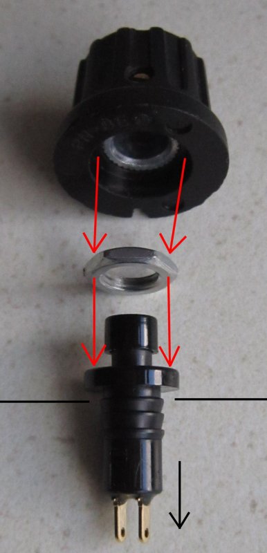
5. The on/off switch has an anti-rotation ridge that makes its diameter larger at that point. File a notch in the box to avoid crushing the switch.
6. The pots have a protrusion to prevent body rotation. These are not needed and can be cut off with side-cutters or hacksaw.
7. If the Inertia pot is not installed, Pin6 must be grounded to prevent random motor behavior.
8. The Tx2 module can be protected with with the heatshrink covering provided.
CALIBRATION:
The motor control pot (Ch1) has a 'click' at the center position. When Throttle is used 'center off' it needs to center accurately so that the 'click' on the Tx matches the 'off' position in DelTang receivers. The 12-way Selecta and Menu switches (Ch2/7) should also be calibrated so they associate the same value for each position as other units. Calibration is done using the Bind button while Tx72 is on. After pressing the Bind button for ~20s Ch1 is calibrated, after another 5s Ch2 is calibrated and after another 5s Ch7 is calibrated.
1. Switch Tx72 on. The led will come on.
2. Rotate the Inertia button fully anti-clockwise (left) so it has no effect on Throttle.
3. Center the Motor pot.
4. Put the 12-way Selecta/Menu switches in the 6 o'clock position (assuming position '1' is at 1 o'clock).
5. Press and hold the Bind button for ~20s until the led goes off. Ch1 should now be calibrated.
6. Continue holding to calibrate Ch2. The led will come on for 3s then the led will go off again.
6. Continue holding to calibrate Ch7. The led will come on for 3s then the led will go off again.
8. Release the Bind button. The led will come back on.