
|
|
Rx102 Instructions (v110)
|
 servo |
 lights |
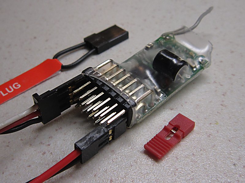
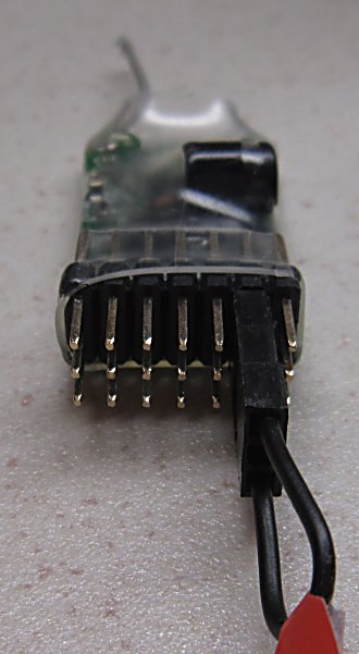
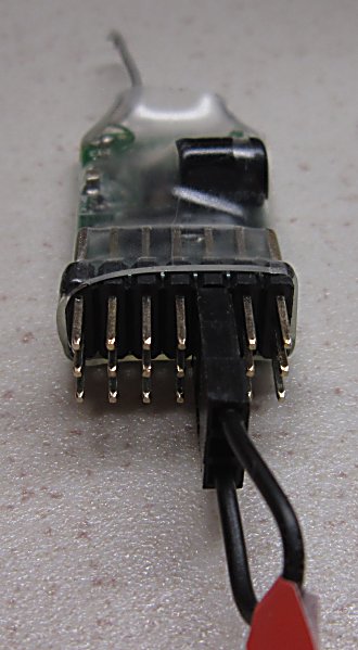
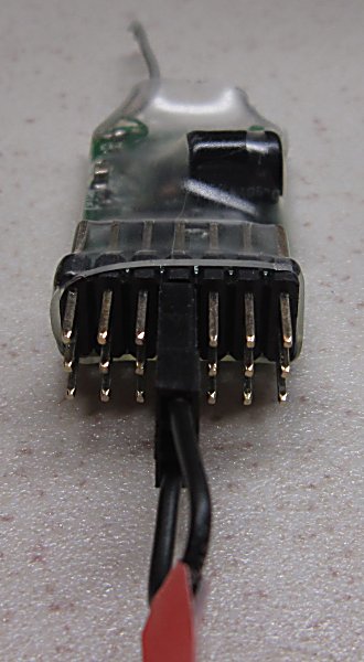
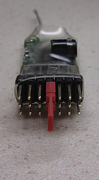
 Connections |
1. DESCRIPTION:
Receiver with servo and directional light outputs intended mainly for trains.
The servo outputs can control servos or an external motor controller (ESC) which are not supplied.
Compatible with all DSM2 transmitters. Power with 3.2v - 10v DC (5v recommended).
2. FEATURES:
Rx102 is available in 3 variants. Each has a different set of features.
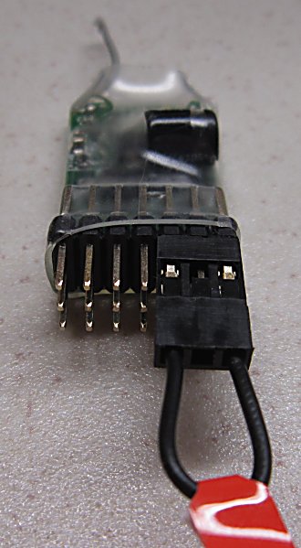
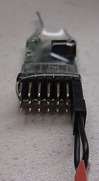
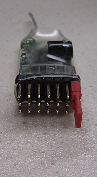
Each receiver has 8 outputs but 7 are more accessible than the 8th.
The primary purpose and what each output does is described below:
|
Rx102-1 |
Rx102-2 |
Rx102-3 |
Comment |
|
| Purpose: |
Loco with joystick Tx Loco with Tx20/21 Loco with Tx22/24 Loco 1 with Tx23 |
Loco 2 with Tx23 |
Loco 3 with Tx23 |
|
| Pin1: | Ch1 Servo [Throttle] | Ch2 Servo [Throttle] | Ch6 Servo [Throttle] | Adjustable throws |
| Pin2: |
Ch4 Servo |
Ch3 Servo |
Ch5 Servo |
Adjustable throws |
| Pin3: |
Ch3 Servo [Direction] |
Ch5 Servo [Direction] |
Ch7 Servo [Direction] |
Adjustable throws |
| Pin4: |
Ch2 Servo |
Ch1 On/Off |
Ch3 On/Off |
. |
| Pin5: |
Ch5 Servo |
Ch7 On/Off |
Ch6 On/Off |
. |
| Pin6: |
Front light |
Front light |
Front light |
Auto directional lights |
| Pin7: |
Rear light |
Rear light |
Rear light |
Auto directional lights |
| Pin8 (side): |
Ch6 Servo |
Ch4 On/Off |
Ch5 On/Off |
. |
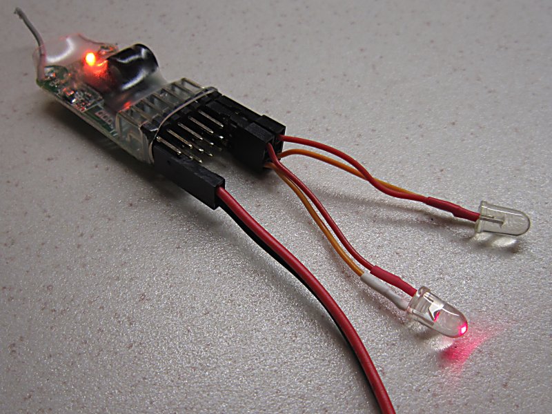
3. LED:
Led On = perfect reception (real-time indicator).
Slow flash = no signal/scanning (~2sec between flashes).
4. CRUISE CONTROL / FAILSAFE:
Outputs do nothing (are not driven) on startup while scanning for a signal.
Outputs 'hold' on signal loss or the transmitter is switched off (cruise control).
Outputs 'hold' when Selecta is enabled and the receiver is not selected.
5. BINDING:
Binding and memorising Selecta switch position.
 |
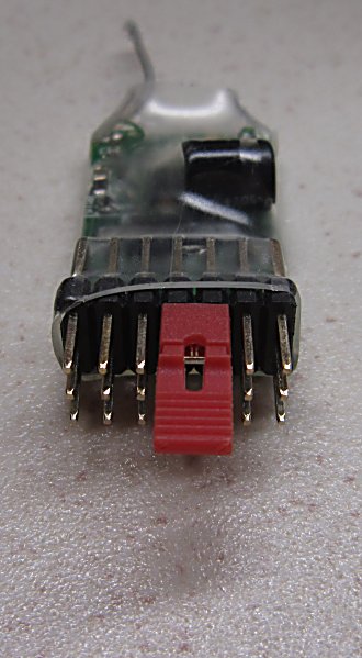
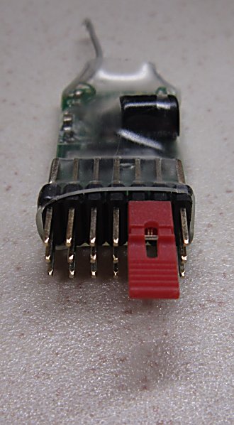
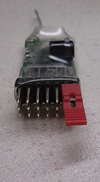
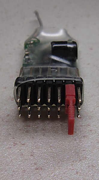
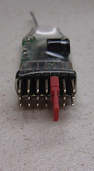
1. Put the large bind plug on Signal pins 5 & 7. Switch Rx on. Led will flash rapidly. Remove bind plug at any time. 2. Choose a Selecta switch position on the Tx (Ch2). 3. Hold Tx bind switch and switch Tx on. Led should flash slower for several seconds. 4. Bind is complete when Led stays On. |
If Led does not come on within 10sec or continues flashing every 2sec (=scanning) the bind has failed. Switch Tx and Rx off, move them closer or further apart and retry. Binding is most reliable when no other RC 2.4 Tx’s are on.
6. SELECTA:
Selecta allows models to be brought in and out of service via the radio without touching them.
Outputs ‘hold’ last position immediately the receiver becomes 'not selected'.
Ch2 is used exclusively for Selecta when enabled.
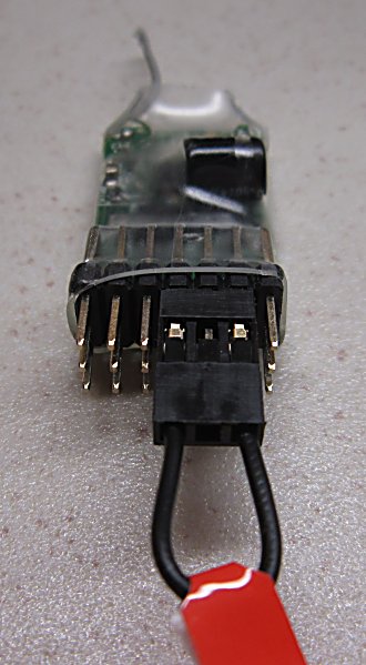 |
To toggle whether Selecta is enabled or disabled: 1. Put the large bind plug on Signal pins 4 & 6. 2. Switch the receiver ON and remove the plug. |
Although mainly intended for use with Tx22, Selecta can be used with a joystick transmitter using the Ch2 trim to select models.
Each model is 'active' when the trim is within a 7 click range (3 clicks left and right of the position memorised during binding).
7. DIRECTIONAL LIGHTING:
Pin6 and Pin7 can drive Front and Rear lights (leds) on a train.
They follow Ch1 for Throttle (and Ch3 for Direction when 'low off' is enabled).
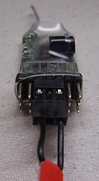 |
To toggle whether Directional Lights operate as 'low off' or 'center off': 1. Put the large bind plug on Signal pins 3 & 5. 2. Switch the receiver ON and remove the plug. |
These pins are 3.1v when on and 0v when off.
They have on-board 180ohm resistors so limit current through leds to around 12mA without needing external resistors.
Connect the led between the Signal pin and Negative (-).
8. ON / OFF SWITCHING:
The designated output is normally ON (3.1v) when the controlling channel is LOW, and OFF in other positions.
These pins have on-board 180ohm resistors so limit current to around 12mA.
Connect an Led between the Signal pin and Negative (-).
From v110-3, three channel positions are recognised, LOW, MID and HIGH.
These outputs can also be 'normally off' (idle low) or 'normally on' (inverted).
This makes it more suitable for driving external logic circuits.
9. EMERGENCY STOP:
Throttle (Ch1) is reduced progressively to a close if an 'Emergency Stop' button is pressed on the transmitter (Ch7 low).
Once released, Throttle has to be closed to allow the output to work again.
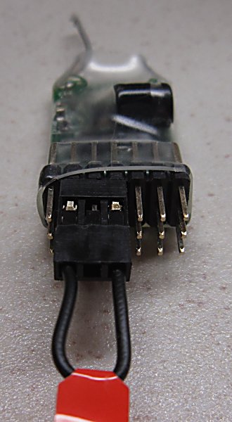 |
To toggle whether Emergency Stop is enabled or disabled: 1. Put the large bind plug on Signal pins 2 & 4. 2. Switch the receiver ON and remove the plug. |
When Directional Lighting is set to 'center off' Ch1 is taken to the mid/neutral position.
When Directional Lighting is set to 'low off' Ch1 is made 'low'.
10. CHANGING SERVO SETTINGS:
Throws, centering and direction of channels associated with Pin1, Pin2 and Pin3 can be changed.
Phase 1 - Select the output to change:
 |
 |
 |
Change Pin1, Pin2 or Pin3. Only one channel can be changed per startup. |
1. To change Pin 1 (Ch1) put the small bind plug on Signal pins 4 & 5 [Throttle].
2. To change Pin 2 (Ch4) put the small bind plug on Signal pins 5 & 6.
3. To change Pin 3 (Ch3) put the small bind plug on Signal pins 6 & 7 [Direction].
4. Switch Rx on. Led will toggle every 1/2 second. Remove bind plug.
5. Switch Tx on. Led will flash once every 2s until it locks on to the Tx signal and then stay off. A servo on the chosen Pin can then be controlled with the Tx.
Phase 2 - Make changes to the selected output:
Changes are made by connecting the Signal pin to Positive(+) or Negtive(-).
Only the output being changed works while making changes to it.
Low and High side throws can be changed by up to 16 steps each way.
The middle Neutral position can be changed by up to 32 steps each way.
The led will flash and throws will change one step per second while a plug is installed.
The led stays on for 3s when throws are returned to their 'mid' position.
The led stays on solid when you reach the end of the adjustment range.
 |
 |
High side Throws 6. To increase high side throws, use the large bind plug to connect the Pin7 signal pin to negative. 7. To decrease high side throws, use the small bind plug to connect the Pin7 signal pin to positive. |
 |
 |
Neutral 8. To move the center position 'up', use the large bind plug to connect the Pin6 signal pin to negative. 9. To move the center position 'down', use the small bind plug to connect the Pin6 signal pin to positive. |
 |
 |
Low side Throws 10. To increase low side throws, use the large bind plug to connect the Pin5 signal pin to negative. 11. To decrease low side throws, use the small bind plug to connect the Pin5 signal pin to positive. |
 |
 |
Reverse 12. To make channel direction 'reversed', use the large bind plug to connect the Pin4 signal pin to negative. 13. To make channel direction 'normal', use the small bind plug to connect the Pin4 signal pin to positive. |
14. Changes are saved whenever you remove a plug.
15. Remove all plugs and switch the Rx off and on to use all outputs normally.
11. PROGRAMMING:
All Rx102 variants have the same core software but with different features enabled on each Pin to make them more suitable for the stated purpose.
All of the 8 outputs can be changed by the user with Prog3 or Prog4 to any of the available functions and can be controlled with any channel number.
Programming options available can be found here.
To minimise stock holdings, shops can change variants with PROG2.
12. PREVIOUS VERSIONS:
v266